
Ultrasound acoustic assemblies and methods of manufacture

a technology of ultrasonic transducer and assembly, applied in the field of ultrasonic transducer assembly, can solve the problems of significant muting challenges, arrays are limited by the available routing density, and the performance of a large area transducer array is significantly degraded

Active Publication Date: 2013-10-03
GENERAL ELECTRIC CO
View PDF6 Cites 32 Cited by
  • Summary
  • Abstract
  • Description
  • Claims
  • Application Information

AI Technical Summary

Benefits of technology

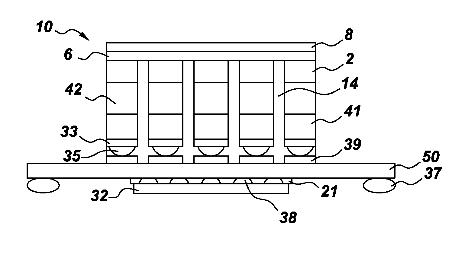
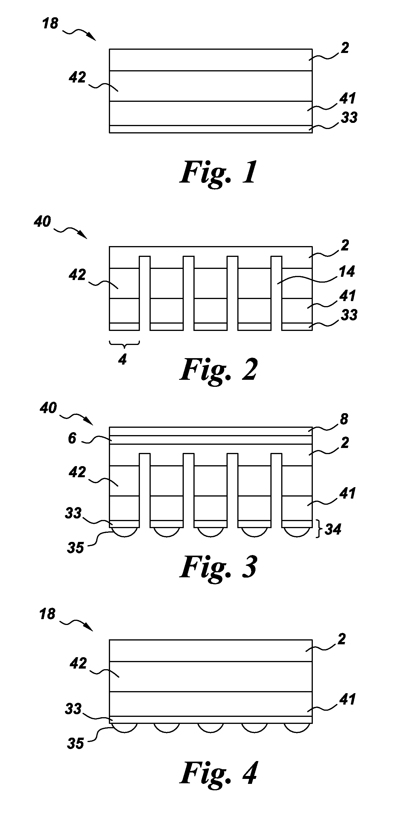
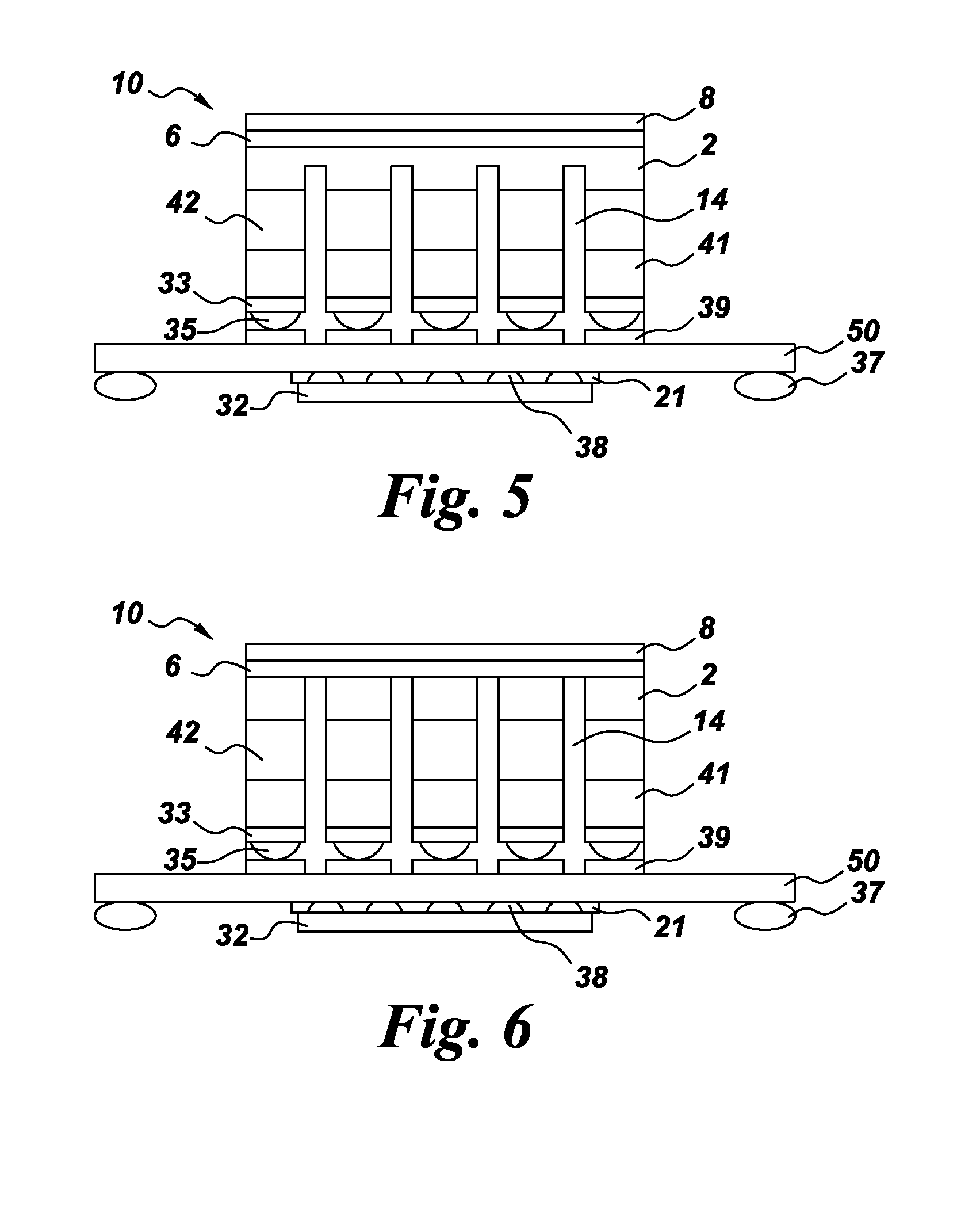
The present invention is about an ultrasound acoustic assembly and a method of manufacturing it. The assembly has a number of ultrasound acoustic arrays, each containing a piezoelectric layer, an acoustic impedance dematching layer, and a support layer. The array has several Dicing kerfs (small cuts) that separate neighboring elements. The assembly also includes application specific integrated circuit (ASIC) dies that are connected to the acoustic arrays, forming acoustic-electric transducer modules. The method of manufacturing involves dicing the acoustic stack, connecting it to the ASIC dies, and depositing under-bump metallization and conductive bumps for electrical connections. These features contribute to the assembly's improved performance and reliability.

Problems solved by technology

Fabricating the transducer array and the electronics array, and coupling the two arrays together, provides a number of design challenges.
For example, performance of a large area transducer array is significantly degraded when there are significant variations in the spacing between modules.
Further, for many current medium-sized arrays, significant muting challenges exist to bring the connections from the nearby electronics into the sensor array.
In addition, these arrays are limited by the available routing density and also by the parasitic capacitances of the traces.

Method used


Image

  • Ultrasound acoustic assemblies and methods of manufacture
  • Ultrasound acoustic assemblies and methods of manufacture
  • Ultrasound acoustic assemblies and methods of manufacture

Examples


Embodiment Construction

[0025]The terms “first,”“second,” and the like, herein do not denote any order, quantity, or importance, but rather are used to distinguish one element from another. The terms “a” and “an” herein do not denote a limitation of quantity, but rather denote the presence of at least one of the referenced items. The modifier “about” used in connection with a quantity is inclusive of the stated value, and has the meaning dictated by context, (e.g., includes the degree of error associated with measurement of the particular quantity). In addition, the term “combination” is inclusive of blends, mixtures, alloys, reaction products, and the like.

[0026]Moreover, in this specification, the suffix “(s)” is usually intended to include both the singular and the plural of the term that it modifies, thereby including one or more of that term (e.g., “the array” may include one or more arrays, unless otherwise specified). Reference throughout the specification to “one embodiment,”“another embodiment,”“a...


PUM

PropertyMeasurementUnit
heightaaaaaaaaaa
thickaaaaaaaaaa
acoustic impedanceaaaaaaaaaa

Abstract

An ultrasound acoustic assembly includes a number of ultrasound acoustic arrays, each array comprising an acoustic stack comprising a piezoelectric layer assembled with at least one acoustic impedance dematching layer and with a support layer. The acoustic stack defines a number of dicing kerfs and a number of acoustic elements, such that the dicing kerfs are formed between neighboring ones of the acoustic elements. The dicing kerfs extend through the piezoelectric layer and through the acoustic impedance dematching layer(s) but extend only partially through the support layer. The ultrasound acoustic assembly further includes a number of application specific integrated circuit (ASIC) die. Each ultrasound acoustic array is coupled to a respective ASIC die to form a respective acoustic-electric transducer module. Methods of manufacture are also provided.

Description

BACKGROUND[0001]The invention relates generally to ultrasonic transducer assemblies and, more particularly, to methods of fabricating ultrasonic transducer assemblies.[0002]Ultrasonic transducer assemblies are typically employed in applications including non-destructive evaluation (NDE) and medical diagnostic imaging, such as ultrasound applications and computed tomography (CT). The ultrasonic transducer assembly generally includes an array of ultrasonic transducers coupled to an electronics array. As explained in commonly assigned U.S. Pat. No. 7,892,176, Robert Wodnicki et al. “Monitoring or imaging system with interconnect structure for large area sensor array,” which is incorporated by reference herein in its entirety, transducer arrays in ultrasound probe assemblies typically span an area no larger than about 20 cm2. For new medical applications, such as screening for internal bleeding and tumors, much larger arrays, on the order of 300 cm2, are required. In non-medical applica...

Claims


Application Information

Patent Timeline
Patent Type & Authority Applications(United States)
IPC IPC(8): H01L41/04H01L41/113H01L41/22H01L41/047
CPCB06B1/0622Y10T29/42H01L41/338H01L2224/16225H01L2224/32225H01L2224/73204H01L2924/1433H01L2924/15321H10N30/088H01L2924/00
Inventor WODNICKI, ROBERT GIDEONBAUMGARTNER, CHARLES EDWARDMILLS, DAVID MARTINDUROCHER, KEVIN MATTHEWHUBER, WILLIAM HULLINGERSOGOIAN, GEORGE CHARLESKAPUSTA, CHRISTOPHER JAMES
Owner GENERAL ELECTRIC CO
Learn More