Lightweight acoustic array

a technology of acoustic arrays and baffles, applied in piezoelectric/electrostrictive transducers, mechanical vibration separation, instruments, etc., can solve the problems of reducing mutual coupling, narrowband inherently, and affecting the operation of arrays employing air-voided baffles,

Active Publication Date: 2011-02-15
LOCKHEED MARTIN CORP
View PDF17 Cites 18 Cited by
  • Summary
  • Abstract
  • Description
  • Claims
  • Application Information

AI Technical Summary

Problems solved by technology

These construction techniques are effective, but due to resonance operation, are inherently narrowband.
As known to those skilled in the art, reduced mutual coupling is beneficial since high inter-element coupling is known to degrade performance of arrays that are electronically steered.
For example, arrays employing air-voided baffles are constrained in operation to relatively shallow depths or suffer reduced performance.
Arrays using inertia plates, screen baffles, resonant absorbers, or active structures typically suffer bandwidth constraints due to the construction that are often more restrictive than the limits of the transducer.
Further yet, many implementations are heavy, leading to an imbalance when transducer arrays are incorporated in ship's hull applications.

Method used


Image

  • Lightweight acoustic array
  • Lightweight acoustic array
  • Lightweight acoustic array

Examples


Embodiment Construction

[0021]It is to be understood that the figures and descriptions of the present invention have been simplified to illustrate concepts that are relevant for a clear understanding of the present invention, while eliminating, for purposes of clarity, many other suitably designed components found in typical sonar systems. However, because such pieces are well known in the art, and because they do not facilitate a better understanding of the present invention, a discussion of such is not provided herein. The disclosure herein is directed to all such variations and modifications known to those skilled in the art.

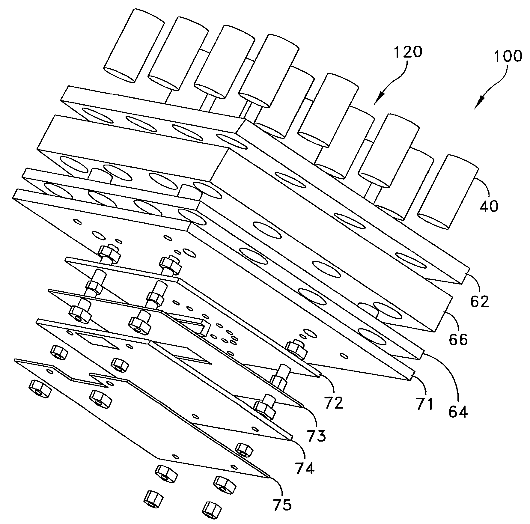
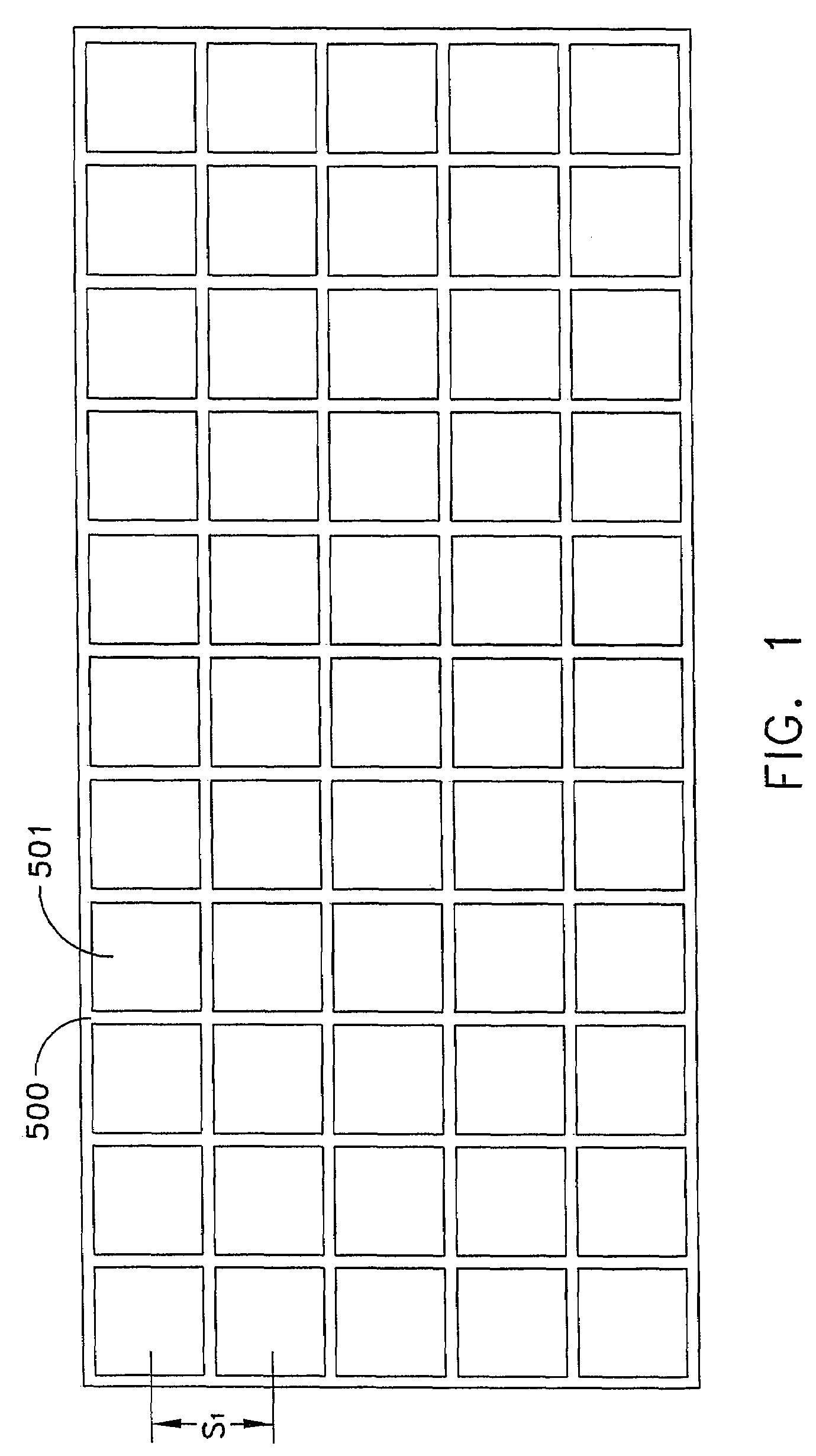
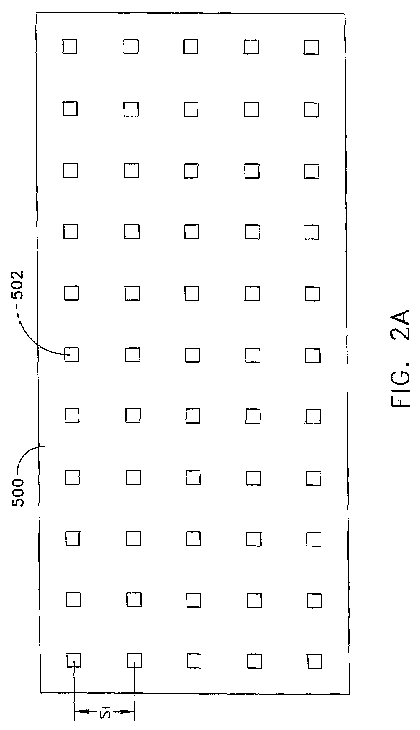
[0022]According to an embodiment of the present invention, an acoustic transducer array and method of baffle construction are presented to provide an improved array for use in underwater installations. In certain embodiments of the invention, exposed baffling material is constructed of an acoustically semi-rigid material and represents a majority of the array's cross-sectional area ...


PUM


Abstract

An acoustic transducer array and method of baffle construction is presented to provide an improved array for use in underwater installations. The array is presented wherein a significant majority of the acoustic energy receiving surface is formed by lightweight acoustic baffling material while still maintaining a fully functional, fully populated array. The acoustic baffle constructed is incompressible and suitable for deep water operation while demonstrating both improved acoustic performance and positive buoyancy when necessary. In addition, the invention eliminates the non-uniform element to element spacing that occurs between sub-panels in similar arrays.

Description

FIELD OF THE INVENTION[0001]The present invention relates generally to underwater acoustic arrays, and more particularly to lightweight, high frequency transducer arrays suitable for conformal installations.BACKGROUND OF THE INVENTION[0002]Electromechanical transducers are devices that exchange electrical and mechanical energy. Such transducers have acoustic applications, such as in microphone, speaker, underwater projector, hydrophone, sonar, sonic cleaning and imaging, and weaponry applications. Transducers intended for sonar applications typically use solid-state piezoelectric elements. These elements may be made from a variety of materials, such as ferroelectric ceramic lead zirconate titanate (PZT).[0003]In sonar applications, a multiplicity of transducers are typically configured in an array. In addition to increased signal gain and reduced interference provided by an array's directivity, operational modes that produce life-like images and yield accurate estimates of contact b...

Claims


Application Information

Patent Timeline
Patent Type & Authority Patents(United States)
IPC IPC(8): H04R17/00
CPCG10K11/008
Inventor GOODMOTE, JOHN H.REINER, DANE E.ERICKSON, DAVID J.
Owner LOCKHEED MARTIN CORP
Why Eureka
Try Eureka