Alignment features for dicing multi element acoustic arrays

a technology of dicing and acoustic arrays, applied in the direction of insulated conductors, flat/ribbon cables, cables, etc., can solve the problems of obscuring signal traces, difficult dicing operation, and inability to use the above-described methods

Active Publication Date: 2008-11-11
FUJIFILM SONOSITE
View PDF4 Cites 21 Cited by
  • Summary
  • Abstract
  • Description
  • Claims
  • Application Information

AI Technical Summary

Benefits of technology

[0009]Various embodiments of the present invention are directed to systems and methods which include alignment markers in the flex circuit that are separate from the signal-carrying conductors. From the markers, scoring marks can be made on the backing block to guide a dicing saw. Alternatively, a dicing saw operator can guide the saw based on the markers, themselves. Example manufacturing techniques connect the signal traces in a buss at the leading edge of the flex circuit, thereby visually obscuring the individual signal traces at the leading edge. Accordingly, various embodiments of the invention may add utility to such techniques by providing alignment markers that are different and / or electrically isolated from the buss and the signal traces.

Problems solved by technology

A difficulty with both methods is that the exposed leading edge of flex circuit 202 is underneath the acoustic stack, thereby obscuring the signal traces and making the dicing operation more challenging.
However, in some applications, discrete signal traces at the leading edges may not be available, making the above-described methods unusable.

Method used


Image

  • Alignment features for dicing multi element acoustic arrays
  • Alignment features for dicing multi element acoustic arrays
  • Alignment features for dicing multi element acoustic arrays

Examples


Embodiment Construction

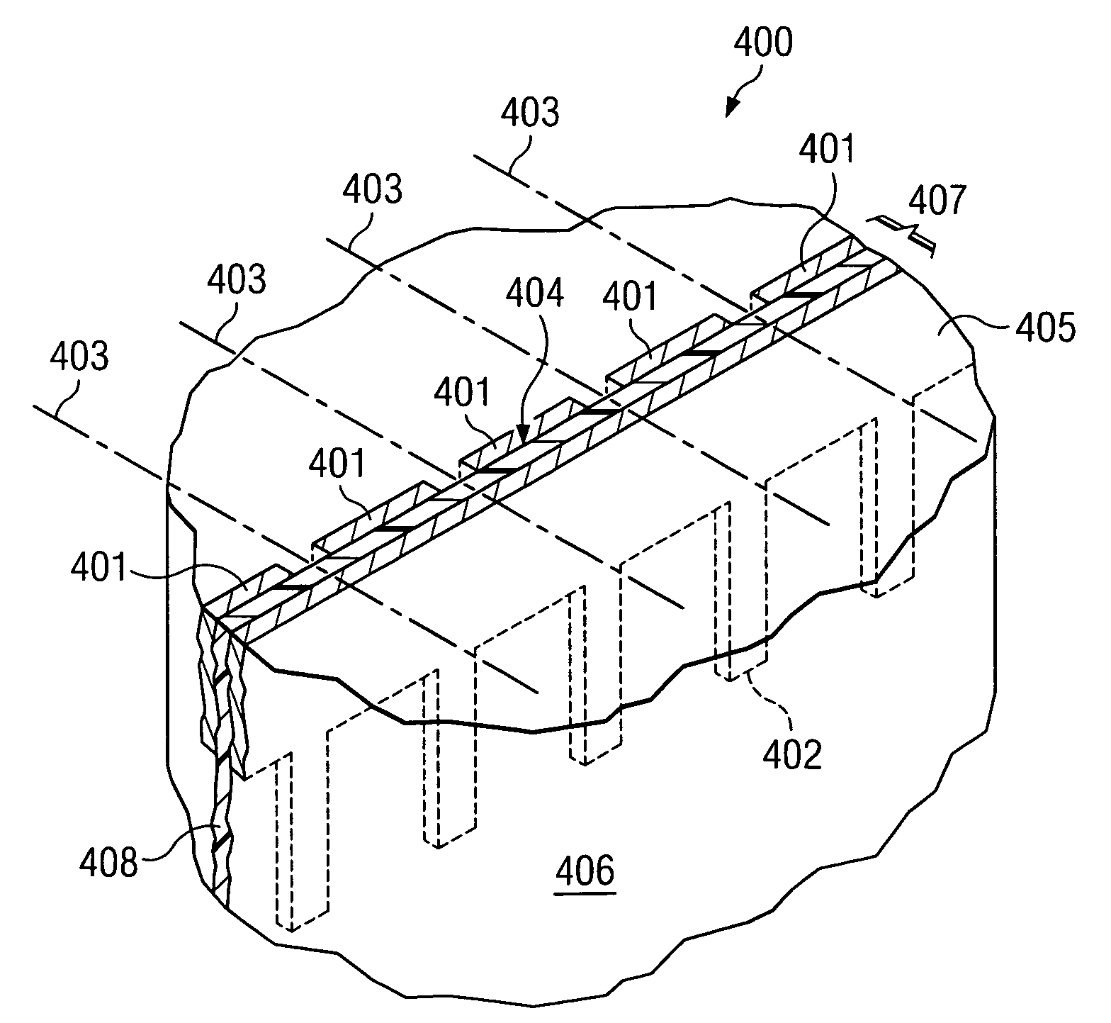
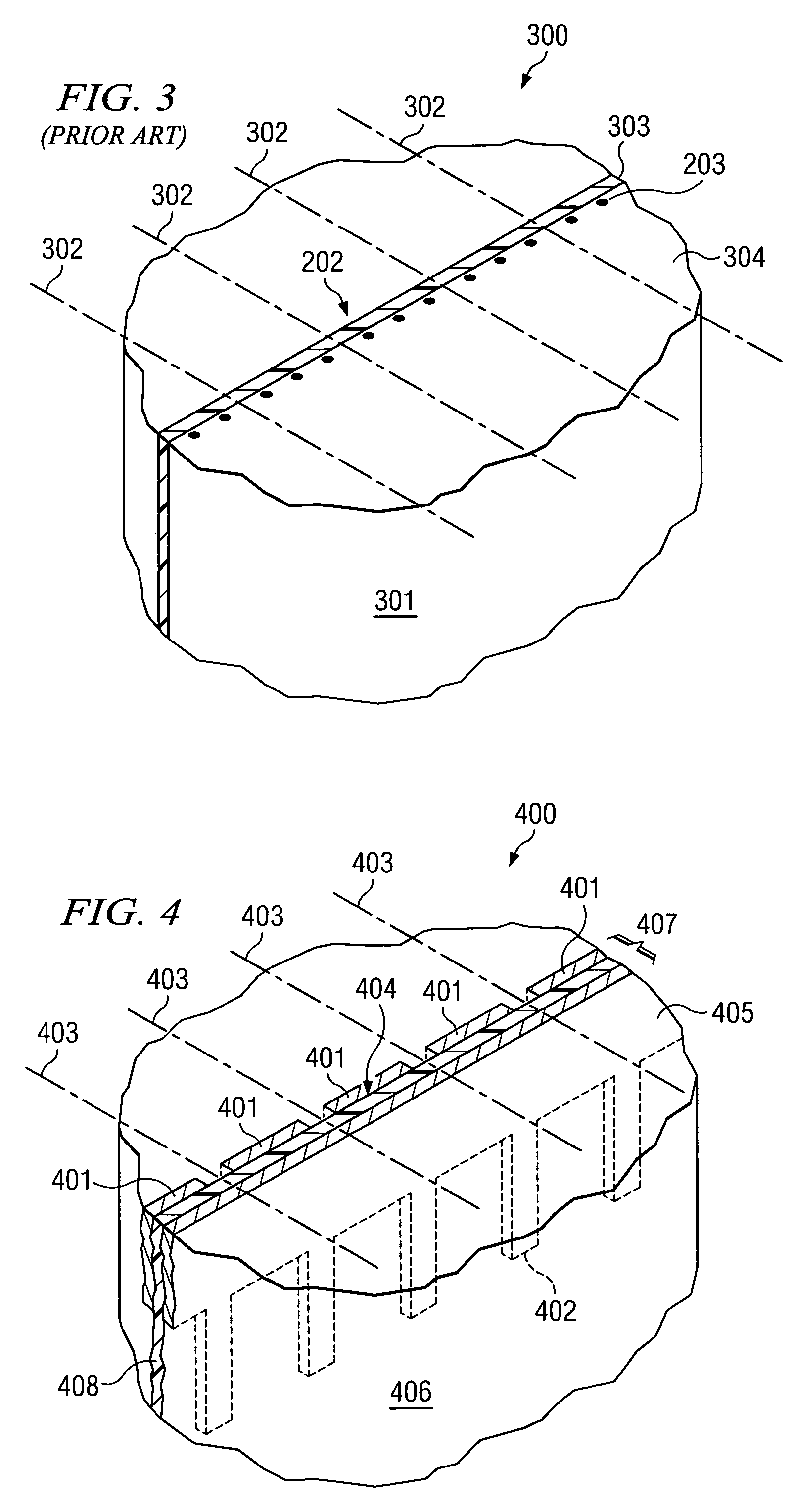
[0020]FIG. 4 is an illustration of example flex circuit assembly 400 according to one embodiment of the invention. Assembly 400 includes backing block 406, and embedded signal traces 402 are present inside backing block 406 but cannot be seen by a human operator. Flex circuit 407 includes buss 404, which terminates and shorts signal traces 402 at the leading edge thereof, so that a human operator sees a line of copper or other conducting material when viewing surface 405. When the operator dices the acoustic stack (not shown), the cuts extend past the depth of buss 404, thereby creating individual contacts out of a once continuous strip of conducting material. Buss 404, once it is diced, provides wide contacts between the transducer elements and their respective signal traces 402. An advantage of using buss 404 rather than individual signal traces at the leading edge of flex circuit 407 is that the buss provides wider contacts, and the reliability and signal conducting quality of a ...


PUM

PropertyMeasurementUnit
flexibleaaaaaaaaaa
conductingaaaaaaaaaa
insulatingaaaaaaaaaa

Abstract

A method and system include a cable including a plurality of conductors terminating at a leading edge of the cable, and markers disposed at the leading edge providing visual reference points at one or more predetermined positions, the markers being separate from the plurality of conductors.

Description

TECHNICAL FIELD[0001]The invention relates in general to manufacturing electronic components and specifically relates to the manufacture of transducer arrays for a variety of systems.BACKGROUND OF THE INVENTION[0002]FIG. 1 is an illustration of example ultrasound transducer 100. Transducer 100 includes, among other things, cable 101 that carries signals between transducer 100 and a processing and control unit (not shown). Transducer 100 also includes body 102 for providing a handle shape for an ultrasound operator to grip transducer 100 when performing an ultrasound examination. Surface 103 of transducer 100 contacts a patient or other subject and includes a plurality of individual transducer elements that transmit and receive acoustic waves during an examination. The processing and control unit controls the beam forming in transducer 100 and also processes the electrical signals produced by the transducer elements as the elements receive reflected acoustic waves during an examinati...

Claims


Application Information

Patent Timeline
Patent Type & Authority Patents(United States)
IPC IPC(8): H01B7/08
CPCH05K1/0269H05K3/0044H05K1/118H05K1/189H05K3/0008H05K2201/053H05K2201/09781H05K2201/09918H05K2203/0228H05K2203/1327
Inventor COLEMAN, ALLAN
Owner FUJIFILM SONOSITE
Why Eureka
Try Eureka