Sound identification method based on cross acoustic array broadband wave beam formation

A cross-shaped, acoustic array technology, applied in the field of acoustic recognition based on the cross-shaped acoustic array broadband beamforming, can solve the problems of background noise enhancement, long-distance recognition rate increase, recognition system being triggered, etc., to improve the signal-to-interference noise ratio , the effect of improving the recognition rate and reliability

Active Publication Date: 2016-10-12
HANGZHOU DIANZI UNIV
View PDF5 Cites 20 Cited by
  • Summary
  • Abstract
  • Description
  • Claims
  • Application Information

AI Technical Summary

Problems solved by technology

[0003] 1. The sound recognition system only needs to recognize signals in a certain direction. However, due to the omnidirectionality of a single microphone, when the recognition object is not near the direction, the recognition system will still be triggered, resulting in false alarms
[0004] 2. In the real complex environment, there are many kinds of interference sound sources and serious background noise near the recognition object, which will cause the overall recognition rate of the system to drop sharply, and the false alarm rate and missed alarm rate will rise sharply
[0005] 3. In practical applications, in order to increase the limit distance of the recognition system's action area, a high-sensitivity microphone will be used. However, a high-sensitivity microphone will inevitably lead to an increase in background noise, resulting in a low recognition rate for long distances. There is a significant increase, but it will decrease

Method used


Image

  • Sound identification method based on cross acoustic array broadband wave beam formation
  • Sound identification method based on cross acoustic array broadband wave beam formation
  • Sound identification method based on cross acoustic array broadband wave beam formation

Examples


Embodiment Construction

[0055] The present invention will be described in detail below in conjunction with the accompanying drawings and specific embodiments. The following description is only for demonstration and explanation, and does not limit the present invention in any form.

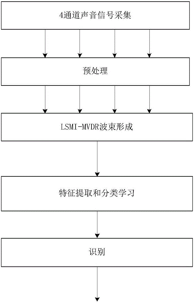
[0056] Such as Figure 4 Shown is the structural diagram of the 4-channel cross-shaped acoustic array established in the Cartesian coordinate system, where d is the distance between two adjacent microphones; r is the radius of the cross-shaped array; S(t) is the sound source, and its direction is θ; A, B, C, and D in the figure correspond to channel 1, channel 2, channel 3, and channel 4, respectively. Assuming that only the signal in the 0-degree direction needs to be identified, align channel 1 of the cross-shaped acoustic array with the 0-degree direction, that is, at Figure 4 , so that the sound source is located on the positive semi-axis of the x-axis, and then collect the signal, a total of 4 channel signals will ...


PUM


Abstract

The invention discloses a sound identification method based on a cross acoustic array broadband wave beam formation. The sound identification method comprises steps of using a cross acoustic array to align with a needed direction to collect acoustic signals, 2, performing pre-processing on collected sound, 3, performing DFT (discrete Fourier transform) on processed data of each frame, performing frequency band extraction according to a needed frequency band, 4, performing LSMI-MVDR wave beam formation on the needed direction by the extracted frequency band, 5, performing inverse DFT on a frequency domain signal after the wave beam is formed, 6, performing frame overlapping synthesis according to the framing principle to output a signal, and 7, performing characteristic extraction and classification study and identification. The sound identification method based on cross acoustic array broadband wave beam formation can improve a signal-to-noise ratio of the signal received in an expected direction, inhibits interference signals of other directions, can be applied to a signal processing process of an acoustic identification system and can effectively improve an identification rate and reliability of the identification system on the identification object.

Description

technical field [0001] The invention belongs to the technical field of signal processing, and in particular relates to an acoustic recognition method based on broadband beamforming of a cross-shaped acoustic array. Background technique [0002] In the traditional single-microphone sound recognition system, there are several problems as follows: [0003] 1. The sound recognition system only needs to recognize signals in a certain direction. However, due to the omnidirectionality of a single microphone, when the recognition object is not near the direction, the recognition system will still be triggered, resulting in false alarms. [0004] 2. In a real complex environment, there are many kinds of interference sound sources and serious background noise near the recognition object, which will cause the overall recognition rate of the system to drop sharply, and the false alarm rate and missed alarm rate will rise sharply. [0005] 3. In practical applications, in order to incre...

Claims


Application Information

Patent Timeline
Patent Type & Authority Applications(China)
IPC IPC(8): G10L17/20G01H17/00
Inventor 王天磊王建中曹九稳赖晓平
Owner HANGZHOU DIANZI UNIV
Why Eureka
Try Eureka