
Piezoelectric Component

a technology of piezoelectric components and components, applied in piezoelectric/electrostrictive/magnetostrictive devices, piezoelectric/electrostriction/magnetostriction machines, electrical equipment, etc., can solve the problems of relatively high probability of voltage flashover between electrodes in the input and output regions of the transformer, and reduce the efficiency of piezoelectric transformers, so as to achieve very efficient conversion of electrical energy

Active Publication Date: 2013-10-03
EPCOS AG
View PDF7 Cites 3 Cited by
  • Summary
  • Abstract
  • Description
  • Claims
  • Application Information

AI Technical Summary

Benefits of technology

The patent describes a piezoelectric component with improved insulation and increased efficiency. The component has special electrodes that are arranged in a way that increases the flashover voltage, which is the minimum voltage needed to initiate an electrical flashover in a component. The electrodes also improve the mechanical energy conversion. The component can be produced using conventional technologies and has additional insulating layers on the top and bottom surfaces to further improve insulation. Overall, the piezoelectric component described in this patent has improved performance and can be more easily produced.

Problems solved by technology

However, this so-called stack design of a piezoelectric transformer has some problems regarding production and electrical insulation between the input and output sides of the transformer.
One problem with this construction, however, is the relatively high probability of a voltage flashover between electrodes in the input region and output region of the transformer which are arranged on the same surface of a layer.
This problem occurs particularly in the case of polarization and generally at high voltages between the electrodes in the input and output regions.
However, if the insulating regions are accordingly enlarged, the efficiency of the piezoelectric transformer decreases.

Method used


Image

  • Piezoelectric Component
  • Piezoelectric Component
  • Piezoelectric Component

Examples


Embodiment Construction

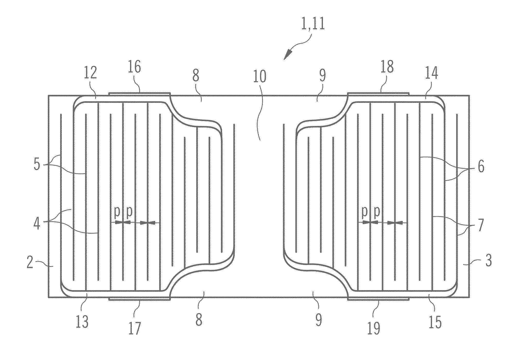
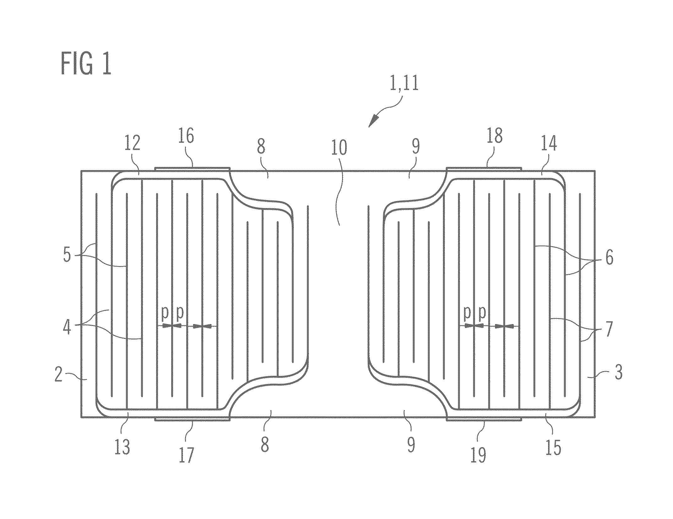
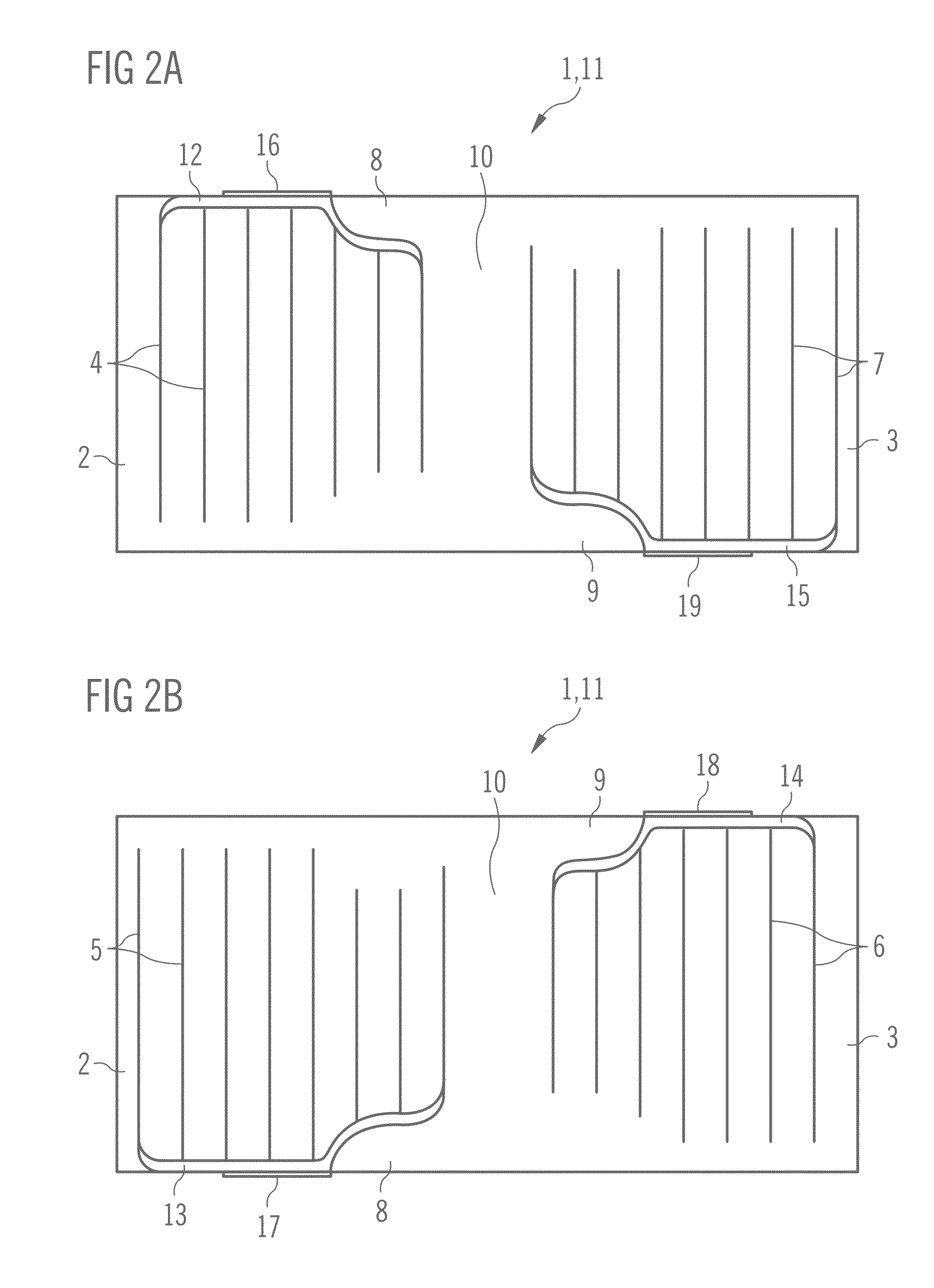
[0036]FIG. 1 shows a piezoelectric transformer that operates with longitudinal oscillations and comprises a base body 1 in a longitudinal section parallel to a top side of the piezoelectric base body 1. The rectangular-parallelepipedal base body 1 composed of piezoelectric material comprises an input region 2 and an output region 3, which are situated at opposite longitudinal ends of the base body 1. The input region 2 is mechanically coupled to the output region 3. The rectangular-parallelepipedal base body 1 has a multilayer structure comprising a plurality of rectangular-parallelepipedal layers 11 stacked one above another parallel to the top side of the base body 1. The top side of the base body 1 is defined by means of one of the largest surface sections of the rectangular-parallelepipedal base body 1.

[0037]Furthermore, the piezoelectric component comprises first and second primary electrodes 4, 5 in the interior of the input region 2 and first and second secondary electrodes 6...


PUM


Abstract

A piezoelectric component comprises a parallelepipedal basic body made of piezoelectric material which has an input region and an output region at opposite longitudinal ends of the basic body. Furthermore, the piezoelectric component comprises first and second primary electrodes which are arranged inside the input region and first and second secondary electrodes which are arranged inside the output region. The primary electrodes are at a greater interval from longitudinal lateral faces of the basic body in a subregion which faces the output region than in the subregion which is remote from the output region. Likewise, the secondary electrodes are at a greater interval from the longitudinal lateral faces of the basic body in a subregion which faces the input region than in a subregion which is remote from the input region.

Description

[0001]This patent application is a national phase filing under section 371 of PCT / EP2011 / 070141, filed Nov. 15, 2011, which claims the priority of German patent application 10 2010 051 444.6, filed Nov. 15, 2010, each of which is incorporated herein by reference in its entirety.TECHNICAL FIELD[0002]The invention relates to a piezoelectric component, in particular a transformer.BACKGROUND[0003]The efficiency of a piezoelectric component is dependent on the values of the mechanical quality factor Qm and of the coupling coefficient KIJ. The coupling coefficient KIJ is a measure of the effectiveness of the conversion of electrical energy into mechanical energy, and vice versa. For many piezoelectric materials, the coupling coefficient K33 has the highest value. This corresponds to an arrangement in which the mechanical oscillations in the piezoelectric component are excited along the length of the piezoelectric base body. Furthermore, the electrodes are arranged at right angles with res...

Claims


Application Information

Patent Timeline
IPC IPC(8): H01L41/107H01L41/047
CPCH01L41/107H01L41/0471H10N30/871H10N30/40
Inventor KARTASHEV, IGORKRAXNER, PETERPUFF, MARKUS
Owner EPCOS AG
Learn More