Liquid crystal display device

a liquid crystal display and display screen technology, applied in non-linear optics, instruments, optics, etc., can solve the problems of difficult to secure the electrical connection between the conductive rubber and the image display screen, and achieve the effect of increasing the height and increasing the distance from the image display screen

Active Publication Date: 2013-10-03
JAPAN DISPLAY INC
View PDF19 Cites 2 Cited by
  • Summary
  • Abstract
  • Description
  • Claims
  • Application Information

AI Technical Summary

Benefits of technology

[0008](1) According to one aspect of the present invention, there is provided a liquid crystal display device which includes: a liquid crystal display panel which has an image display screen and a back surface on a side opposite to the image display screen; a resin frame which includes a support portion for supporting the liquid crystal display panel at a peripheral portion of the back surface, and a resin frame portion which surrounds the liquid crystal display panel; a metal frame which includes a metal frame portion facing a peripheral portion of the image display screen of the liquid crystal display panel and the resin frame portion; and a conductive elastic sheet which includes: an outer portion which is sandwiched between the resin frame portion and the metal frame portion and is brought into contact with the metal frame portion; an inner portion which is laminated to the image display screen of the liquid crystal display panel; and a connecting portion which connects the outer portion and the inner portion; wherein at least a portion of an upper surface of the resin frame portion is arranged at a higher position than the image display screen, at least a portion of the outer portion of the conductive elastic sheet is arranged at a higher position than the inner portion, the inner portion of the conductive elastic sheet is laminated to the image display screen of the liquid crystal display panel in a flat shape, the conductive elastic sheet has a slit formed between the outer portion and the inner portion and adjacent to the connecting portion, and at least one of the outer portion and the connecting portion of the conductive elastic sheet is bent in a height increasing direction from the same height position as the inner portion. According to the present invention, the conductive elastic sheet has the slit formed between the outer portion and the inner portion and hence, even when at least one of the outer portion and the connecting portion is bent, an action imparted to the inner portion by an elastic force of the conductive elastic sheet is small. Accordingly, the inner portion hardly peels off from the image display screen and hence, it is possible to secure the electrical connection between the conductive elastic sheet which is electrically connected to the metal frame and the image display screen. In the present invention, “height” means the direction that the image display screen faces. The height is increased along with the increase of a distance from the image display screen.

Problems solved by technology

Accordingly, it has been difficult to secure the electrical connection between the conductive rubber and the image display screen.

Method used


Image

  • Liquid crystal display device
  • Liquid crystal display device
  • Liquid crystal display device

Examples


Embodiment Construction

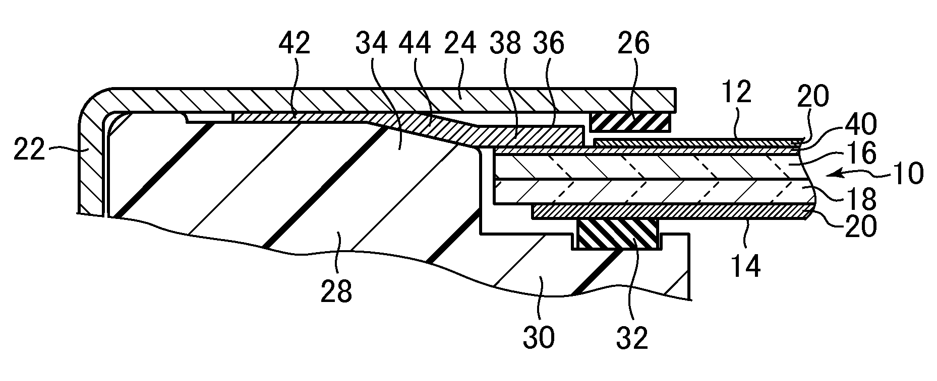
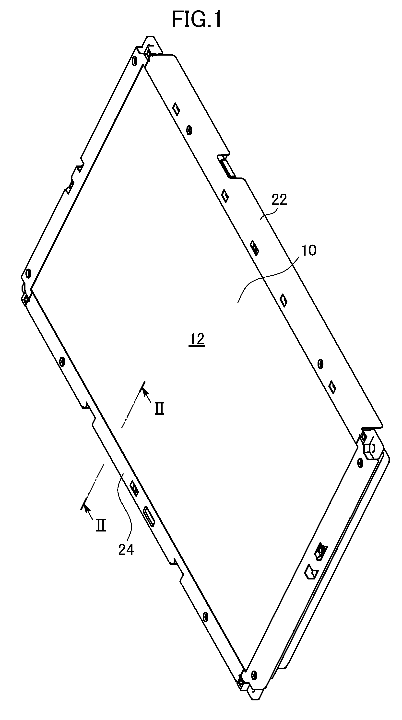
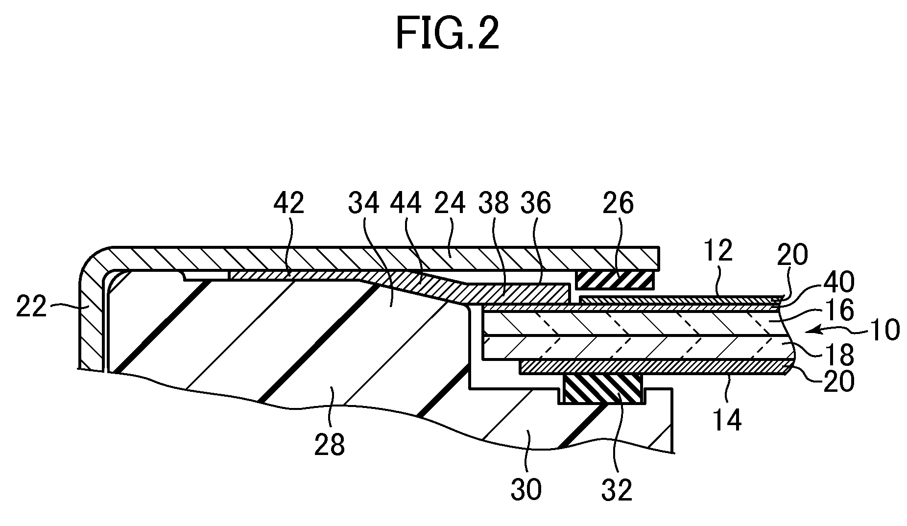
[0019]Hereinafter, embodiments of the present invention are explained in conjunction with drawings. FIG. 1 is a perspective view of a liquid crystal display device according to the embodiment of the present invention. FIG. 2 is an enlarged view of the liquid crystal display device taken along a line II-II in FIG. 1.

[0020]The liquid crystal display device includes a liquid crystal display panel 10. The liquid crystal display panel 10 includes an image display screen 12 arranged on a side where an image is displayed, and a back surface 14 on a side opposite to the image display screen 12. The image display screen 12 has a rectangular planar shape. The liquid crystal display panel 10 includes a pair of substrates 16, 18 (formed of a glass substrate, for example), and a liquid crystal material not shown in the drawing which is arranged between both substrates. A polarizer 20 is arranged on surfaces of the pair of substrates 16, 18 which are opposite to each other. In FIG. 2, the lower s...


PUM

PropertyMeasurementUnit
conductiveaaaaaaaaaa
heightaaaaaaaaaa
shapeaaaaaaaaaa

Abstract

A conductive elastic sheet includes: an outer portion sandwiched between a resin frame portion and a metal frame portion and brought into contact with the metal frame portion; an inner portion laminated to an image display screen; and a connecting portion connecting the outer and inner portions. An upper surface of the resin frame portion is arranged at a higher position than the image display screen. The outer portion of the conductive elastic sheet is arranged at a higher position than the inner portion. The inner portion of the conductive elastic sheet is laminated to the image display screen in a flat shape. The conductive elastic sheet has a slit formed between the outer and inner portions and adjacent to the connecting portion. The connecting portion is bent in a height increasing direction from the same height position as the inner portion.

Description

CROSS-REFERENCE TO RELATED APPLICATION[0001]The present application claims priority from Japanese application JP2012-080996 filed on Mar. 30, 2012, the content of which is hereby incorporated by reference into this application.BACKGROUND OF THE INVENTION[0002]1. Field of the Invention[0003]The present invention relates to a liquid crystal display device.[0004]2. Description of the Related Art[0005]With respect to a liquid crystal display panel, there has been known the structure where static electricity generated on an image display screen of the liquid crystal display panel can be released by laminating conductive rubber to the image display screen (JP 2005-77590A). An edge portion on a back surface side of a display panel is supported on a resin frame. A metal frame is arranged above a peripheral portion of the image display screen of the liquid crystal display panel. To prevent the liquid crystal display panel from coming into contact with the metal frame when the liquid crystal ...

Claims


Application Information

Patent Timeline
Patent Type & Authority Applications(United States)
IPC IPC(8): G02F1/1333
CPCG02F1/133308G02F1/136204G02F2202/22G02F2001/13332G02F2001/133317G02F1/133317G02F1/13332
Inventor FUKAYAMA, NORIHISA
Owner JAPAN DISPLAY INC
Why Eureka
Try Eureka