Image processing device and method
- Summary
- Abstract
- Description
- Claims
- Application Information
AI Technical Summary
Benefits of technology
Problems solved by technology
Method used
Image
Examples
first example
(1) First Example
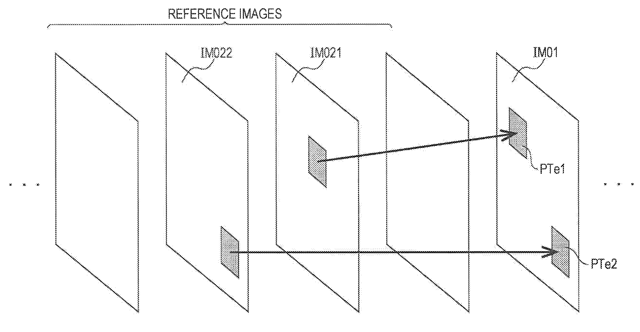
[0153]FIG. 8 is an explanatory diagram illustrating a first example of merge information generated by the merge information generating unit 45 according to the present embodiment. Referencing FIG. 8, a block of interest B10 is shown within an image to be encoded IM10. Blocks B11 and B12 are neighbor blocks at the left and above the block of interest B10, respectively. A motion vector MV10 is a motion vector calculated by the motion vector calculating unit 42 regarding the block of interest B10. The motion vectors MV11 and MV12 are reference motion vectors set to the neighbor blocks B11 and B12, respectively. Further, a co-located block B1col of the block of interest B10 is shown within the reference image IM1ref. The motion vector MV1col is a reference motion vector set to the co-located block B1col.
[0154]In the first example, the motion vector MV10 is the same as all of the reference motion vectors MV11, MV12, and MV1col. In this case, the merge information generat...
second example
(2) Second Example
[0155]FIG. 9 is an explanatory diagram illustrating a second example of merge information generated by the merge information generating unit 45 according to the present embodiment. Referencing FIG. 9, a block of interest B20 is shown within an image to be encoded IM20. Blocks B21 and B22 are neighbor blocks at the left and above the block of interest B20, respectively. A motion vector MV20 is a motion vector calculated by the motion vector calculating unit 42 regarding the block of interest B20. The motion vectors MV21 and MV22 are reference motion vectors set to the neighbor blocks B21 and B22, respectively. Further, a co-located block B2col of the block of interest B20 is shown within the reference image IM2ref. The motion vector MV2col is a reference motion vector set to the co-located block B2col.
[0156]In the second example, the motion vector MV20 is the same as the reference motion vector MV2col. The motion vector MV20 is different from at least one of the ref...
third example
(3) Third Example
[0157]FIG. 10 is an explanatory diagram illustrating a third example of merge information generated by the merge information generating unit 45 according to the present embodiment. Referencing FIG. 10, a block of interest B30 is shown within an image to be encoded IM30. Blocks B31 and B32 are neighbor blocks at the left and above the block of interest B30, respectively. A motion vector MV30 is a motion vector calculated by the motion vector calculating unit 42 regarding the block of interest B30. The motion vectors MV31 and MV32 are reference motion vectors set to the neighbor blocks B31 and B32, respectively. Further, a co-located block B3col of the block of interest B30 is shown within the reference image IM3ref. The motion vector MV3col is a reference motion vector set to the co-located block B3col.
[0158]In the third example, the motion vector MV30 is the same as the reference motion vectors MV31 and MV32. The motion vector MV30 is different from reference motion...
PUM
 Abstract
Description
Claims
Application Information
 - R&D
- Intellectual Property
- Life Sciences
- Materials
- Tech Scout
- Unparalleled Data Quality
- Higher Quality Content
- 60% Fewer Hallucinations
Browse by: Latest US Patents, China's latest patents, Technical Efficacy Thesaurus, Application Domain, Technology Topic, Popular Technical Reports.
© 2025 PatSnap. All rights reserved.Legal|Privacy policy|Modern Slavery Act Transparency Statement|Sitemap|About US| Contact US: help@patsnap.com


