Moving-picture signal coding and/or decoding system resistant to transmission error
Inactive Publication Date: 2011-06-14
KK TOSHIBA
View PDF7 Cites 0 Cited by
Summary
Abstract
Description
Claims
Application Information
AI Technical Summary
This helps you quickly interpret patents by identifying the three key elements:
Problems solved by technology
Method used
Benefits of technology
Benefits of technology
[0016]It is therefore an object of the present invention to provide a moving-picture coding and / or decoding system which can quickly restore if data is lost due to error and in which the increased code amount is less than those of the refresh and the error correction.
Problems solved by technology
However, in such a conventional moving-picture coding and / or decoding system, there are the following problems.
In a channel in which an error may be mixed, such as a radio channel, when only the aforementioned coding is carried out, the quality of the decoded image is remarkably deteriorated if an error occurs.
In particular, when there is an error in a signal such as a synchronizingsignal, a mode data and a motion vector, the picture quality is remarkably deteriorated.
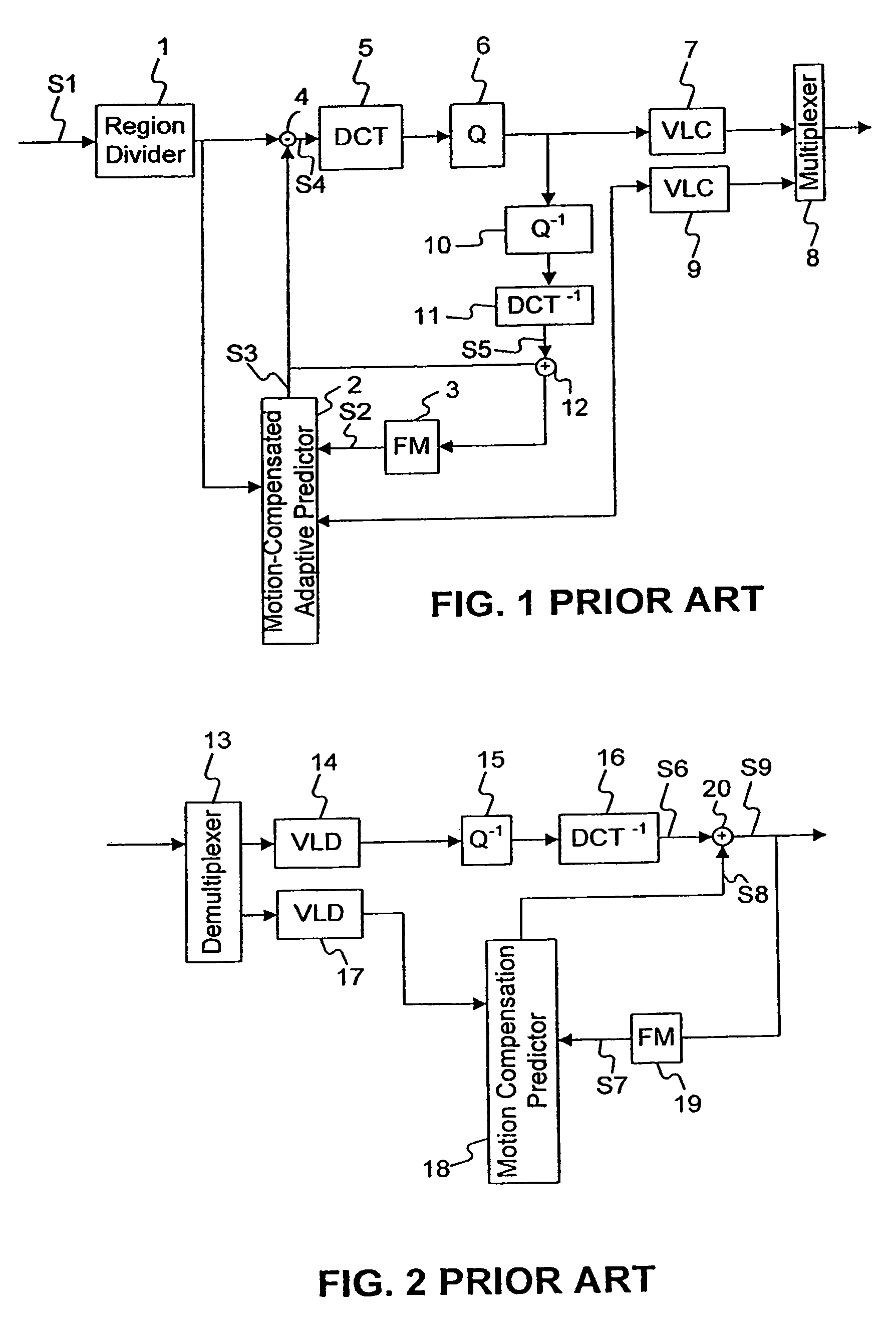
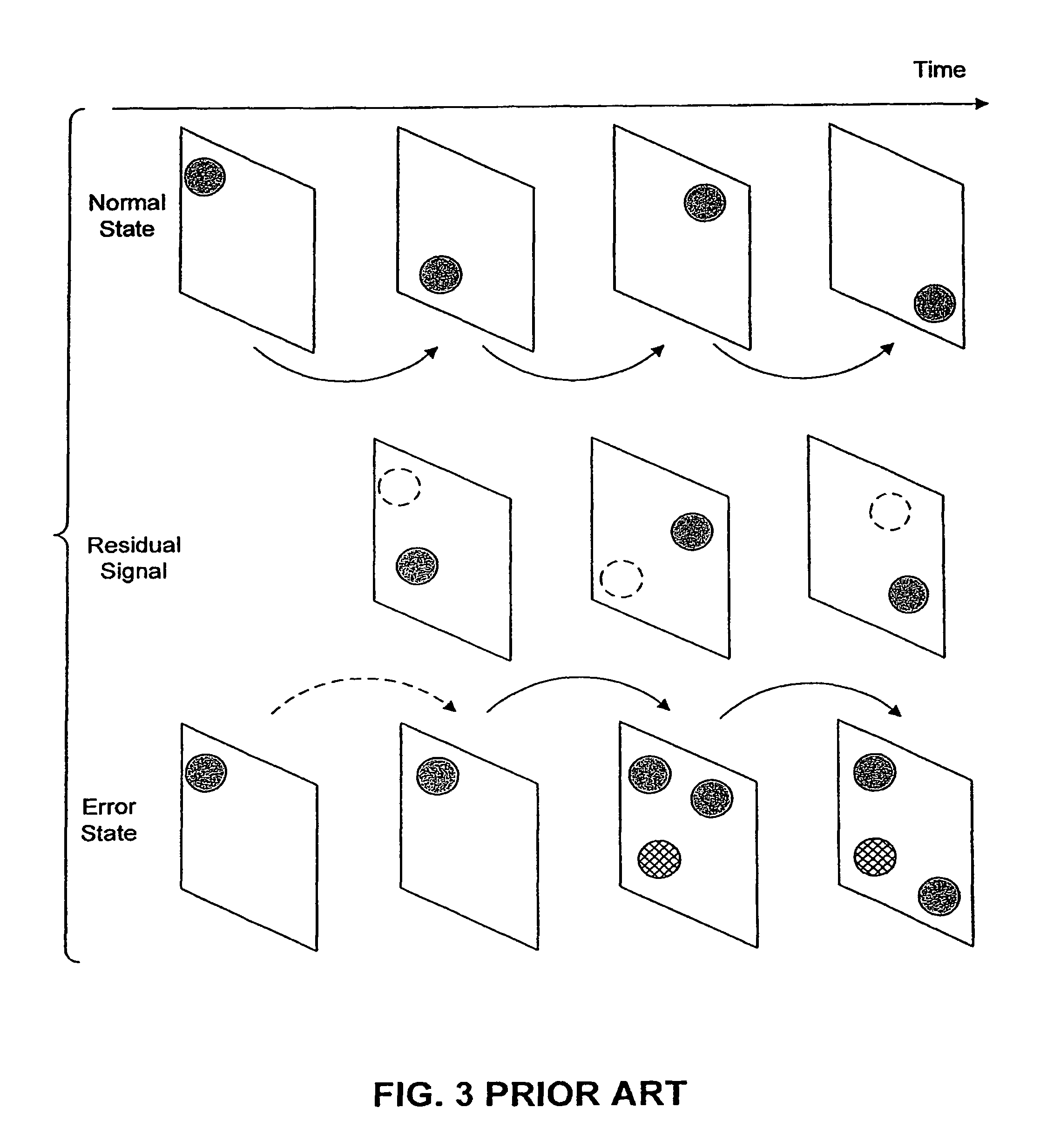
However, since only the interframe difference is coded in the motion-compensated adaptive prediction coding, when an error occurs, the frame is not only incorrect, but an incorrect image is also stored in a frame memory, so that a predicted image is prepared using the incorrect image and a residual error is added thereto.
For that reason, even if the subsequent frame is correctly decoded, it is not possible to obtain a correctly decoded image in the subsequent frame, except that when the data is transmitted in a mode (INTRA mode) wherein the coding is performed in only the frame without using the interframe difference or when the influence of the error is gradually attenuated to return to the original state.
Thereafter, since the residual error is added to the incorrect image, the error is not basically erased, so that it is not possible to reproduce a correctly decoded image.
In this case, when the coding is performed in the INTRA mode, the code amount is increased to remarkably deteriorate the picture quality when no error occurs.
However, although the cyclic refresh is able to resstring the increase of the code string, there is a problem in that it takes a long time until the normal state is restored.
However, if errors of hundreds bits occur at a burst and continuously, it is difficult to correct such errors.
Even if it is possible to correct such errors, a very long redundancy is required.
As mentioned above, in en image coding, particularly in a moving-picture coding, the loss of data due to error greatly deteriorates the picture quality.
In addition, in the conventional methods such as the cyclic refresh for restoring the lost data due to error, there are problems in that it takes a long time until it is restored considering the coding efficiency, and that the attempt to decrease the time required to restore the lost data increases the code amount to lower the efficiency.
Method used
Image
Click on the blue label to locate the original text in one second.
Reading with bidirectional positioning of images and text.
Examples
Embodiment Construction
[0058]Referring now to the drawings, the preferred embodiments of the present invention will be described below.
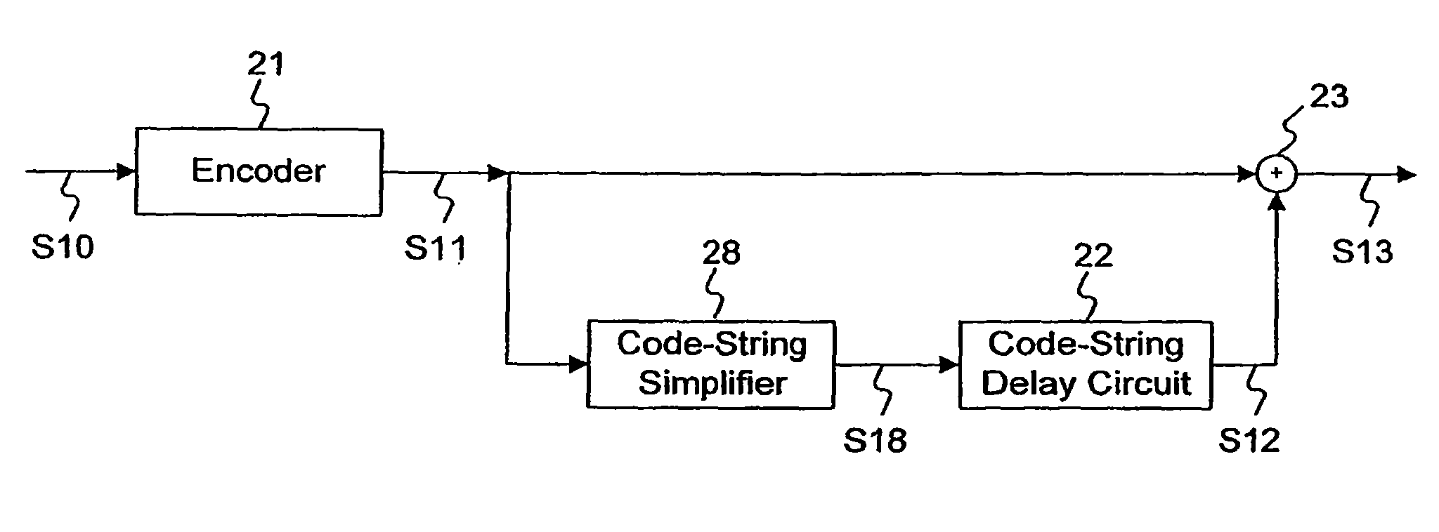
[0059]FIG. 4 is a block diagram of the first preferred embodiment of a moving-picture coding system according to the present invention. An input image signal S10 is coded in an encoder 21 to be outputted as a code string (which will be hereinafter referred to as a “basic code string”). The basic code string S11 is directly inputted to a code-string synthesizer 23. The basic code string S11 is also inputted to a code-string delay circuit 22 wherein it is stored and retained for a predetermined period of time, and then it is outputted.
[0060]That is, the code-string delay circuit 22 outputs the retained past code string (which will be hereinafter referred to as an “additional code string”) S12 after the predetermined period of time. This additional code string S12 is also inputted to the code-string synthesizer 23. In the code-string synthesizer 23, the basic code string S11 ...
PUM
Abstract
An input image signal is coded by an encoder to be outputted as a basic code string, and the basic code string is delayed by a code-string delay circuit for a predetermined period of time to be outputted as an additional code string. The basic code string is synthesized with the additional code string by a code-string synthesizer to be outputted as an output code string. Thus, there is provided an image data coding system which can quickly restore data even if the data is lost due to error and in which the increased code amount is less than the cycle refresh and the error correction.
Description
[0001]More than one reissue application has been filed for the reissue of U.S. Pat. No. 6,701,018. The currently pending reissue applications are applications Ser. Nos. 11 / 366,010; 12 / 232,511; 12 / 654,141; 12 / 762,604; 12 / 762,642; 12 / 762,669; 12 / 232,509; 12 / 654,140; 12 / 763,064; 12 / 763,052; 12 / 763,036; 12 / 762,722; 12 / 272,510; 12 / 591,980; 12 / 762,864; 12 / 762,834; 12 / 762,793; 12 / 762,756; 12 / 762,686; 12 / 272,508; 12 / 591,981; 12 / 762,795; 12 / 762,972; 12 / 762,983; 12 / 762,745; 12 / 762,998; and 12 / 762,935.[0002]This is a divisional reissue application of U.S. reissue application Ser. No. 12 / 591,980, filed Dec. 7, 2009, which is a divisional reissue application of U.S. reissue application Ser. No. 12 / 232,510, filed Sep. 18, 2008, which is a divisional reissue application of U.S. reissue application Ser. No. 11 / 366,010, filed Mar. 2, 2006, now abandoned, which is a reissue application of U.S. Pat. No. 6,701,018, which is a divisional of application Ser. No. 09 / 471,415 filed Dec. 23, 1999, now U.S. P...
Claims
Application Information
Patent Timeline
Application Date:The date an application was filed.
Publication Date:The date a patent or application was officially published.
First Publication Date:The earliest publication date of a patent with the same application number.
Issue Date:Publication date of the patent grant document.
PCT Entry Date:The Entry date of PCT National Phase.
Estimated Expiry Date:The statutory expiry date of a patent right according to the Patent Law, and it is the longest term of protection that the patent right can achieve without the termination of the patent right due to other reasons(Term extension factor has been taken into account ).
Invalid Date:Actual expiry date is based on effective date or publication date of legal transaction data of invalid patent.

