Mold clamping mechanism for injection molding machine

Active Publication Date: 2013-10-03
FANUC LTD
View PDF2 Cites 2 Cited by
  • Summary
  • Abstract
  • Description
  • Claims
  • Application Information

AI Technical Summary

Benefits of technology

The present invention provides a mold clamping mechanism for an injection molding machine that can adjust the stiffness of the mold platen and allow the thickness of a mountable mold to be expanded without increasing the overall length of the machine. This results in a thinner mold platen.

Problems solved by technology

If the stiffness of the mold platen (the fixed platen, the movable platen) is low, the mold (the fixed-side mold, the movable-side mold) deforms together with the mold platen under the application of mold clamping power or injection pressure, so that the precision of a molded article may decrease in some cases.
In general, mold platens need to have a stiffness high enough to support even a mold that requires stiffness, and hence mold platens are provided with an excessive stiffness in some cases.
If a mold platen is made thicker in order to enhance the stiffness of the mold platen, the total machine length is larger, costs are higher, and a space to be secured for machine installation is larger.
Further, this technique does not have an object to adjust the stiffness of the mold platen.
Further, the technique described in Japanese Patent Application Laid-Open No. 09-155929 mentioned above is intended to protect the mold surface, and does not have an object to adjust the stiffness of the mold platen.

Method used


Image

  • Mold clamping mechanism for injection molding machine
  • Mold clamping mechanism for injection molding machine
  • Mold clamping mechanism for injection molding machine

Examples


Embodiment Construction

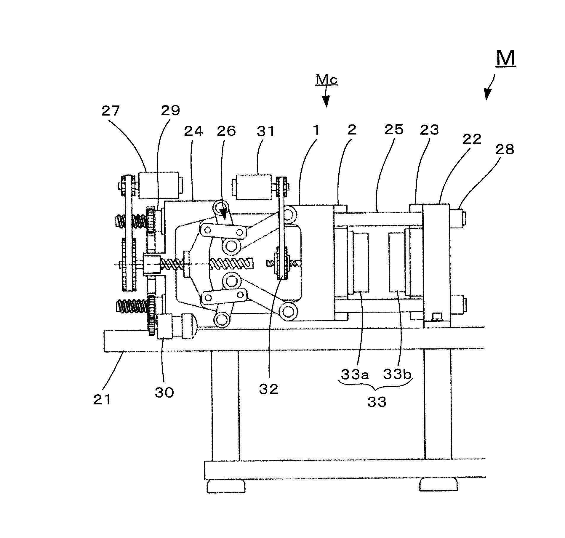
[0026]An embodiment of a mold clamping mechanism for an injection molding machine according to the present invention is described with reference to FIG. 1.

[0027]A mold clamping mechanism Mc for an injection molding machine M includes a fixed platen 22 fixed on a machine base 21, a rear platen 24 that is movably provided at a distance from the fixed platen 22, a plurality of tie bars 25 that couple the fixed platen 22 to the rear platen 24, a movable platen 1 that is provided so as to be movable in the axial direction of the tie bars 25, a toggle-link mechanism 26 that drives the movable platen 1 in a mold closing / opening direction, and a servomotor 27 that drives the toggle-link mechanism 26. The mold clamping mechanism Mc performs closing / opening and clamping of a movable-side mold 33a attached to the movable platen 1 with respect to a fixed-side mold 33b attached to the fixed platen 22.

[0028]A male screw is formed in a portion at one end part of each tie bar 25, the portion passin...


PUM

PropertyMeasurementUnit
Temperatureaaaaaaaaaa
Stiffnessaaaaaaaaaa
Modulusaaaaaaaaaa

Abstract

In a mold clamping mechanism for an injection molding machine, a mold platen stiffness adjusting plate is attached to a mold platen (a movable platen, a fixed platen) at the mold attachment surface thereof. The mold platen stiffness adjusting plate is provided, at the mold attachment surface thereof, with elements for mold attachment that have the same shapes and are arranged on the same places as those provided on the mold platen at the mold attachment surface thereof. Accordingly, the same mold can be attached to the mold platen stiffness adjusting plate attached to the mold platen, and can also be attached to the mold platen from which the mold platen stiffness adjusting plate is detached.

Description

BACKGROUND OF THE INVENTION[0001]1. Field of the Invention[0002]The present invention relates to a mold clamping mechanism for an injection molding machine.[0003]2. Description of the Related Art[0004]An injection molding machine includes an injection apparatus and a mold clamping mechanism on a machine base. The mold clamping mechanism includes a fixed platen installed on the machine base, a plurality of tie bars fixed to an edge portion of the fixed platen, a movable platen that is movably installed along the tie bars, and a toggle mechanism that drives the movable platen. A fixed-side mold is attached to the fixed platen at a surface facing the movable platen. Further, a movable-side mold is attached to the movable platen at a surface facing the fixed platen. The mold is closed / opened by moving the movable platen toward the fixed platen (moving forward) and moving the movable platen in a direction away from the fixed platen (moving backward). A resin that is heated and melted in ...

Claims


Application Information

Patent Timeline
IPC IPC(8): B29C33/20
CPCB29C45/1744B29C33/202B29C45/64B29C45/1751
Inventor TAKATSUGI, SATOSHINISHIMURA, KOICHISENGA, MASATOSHI
Owner FANUC LTD
Why Eureka
Try Eureka