Series-connected couplers for active antenna systems

a technology of active antenna and series connection, applied in the field of radio antenna systems, can solve the problems of the loss of a/b>ti/sub> and a/b>ri/sub> of the downlink and uplink signals, and the inability to achieve the desired value relative to the gain of a/b>ti and a/b>ri

Inactive Publication Date: 2013-10-03
ANDREW LLC
View PDF9 Cites 54 Cited by
  • Summary
  • Abstract
  • Description
  • Claims
  • Application Information

AI Technical Summary

Problems solved by technology

Radio antenna system 100 is typically more complex and costly to implement than comparable prior-art radio antenna systems that process the uplink and downli

Method used


Image

  • Series-connected couplers for active antenna systems
  • Series-connected couplers for active antenna systems
  • Series-connected couplers for active antenna systems

Examples


Embodiment Construction

[0023]Reference herein to “one embodiment” or “an embodiment” means that a particular feature, structure, or characteristic described in connection with the embodiment can be included in at least one embodiment of the invention. The appearances of the phrase “in one embodiment” in various places in the specification are not necessarily all referring to the same embodiment, nor are separate or alternative embodiments necessarily mutually exclusive of other embodiments. The same applies to the term “implementation.”

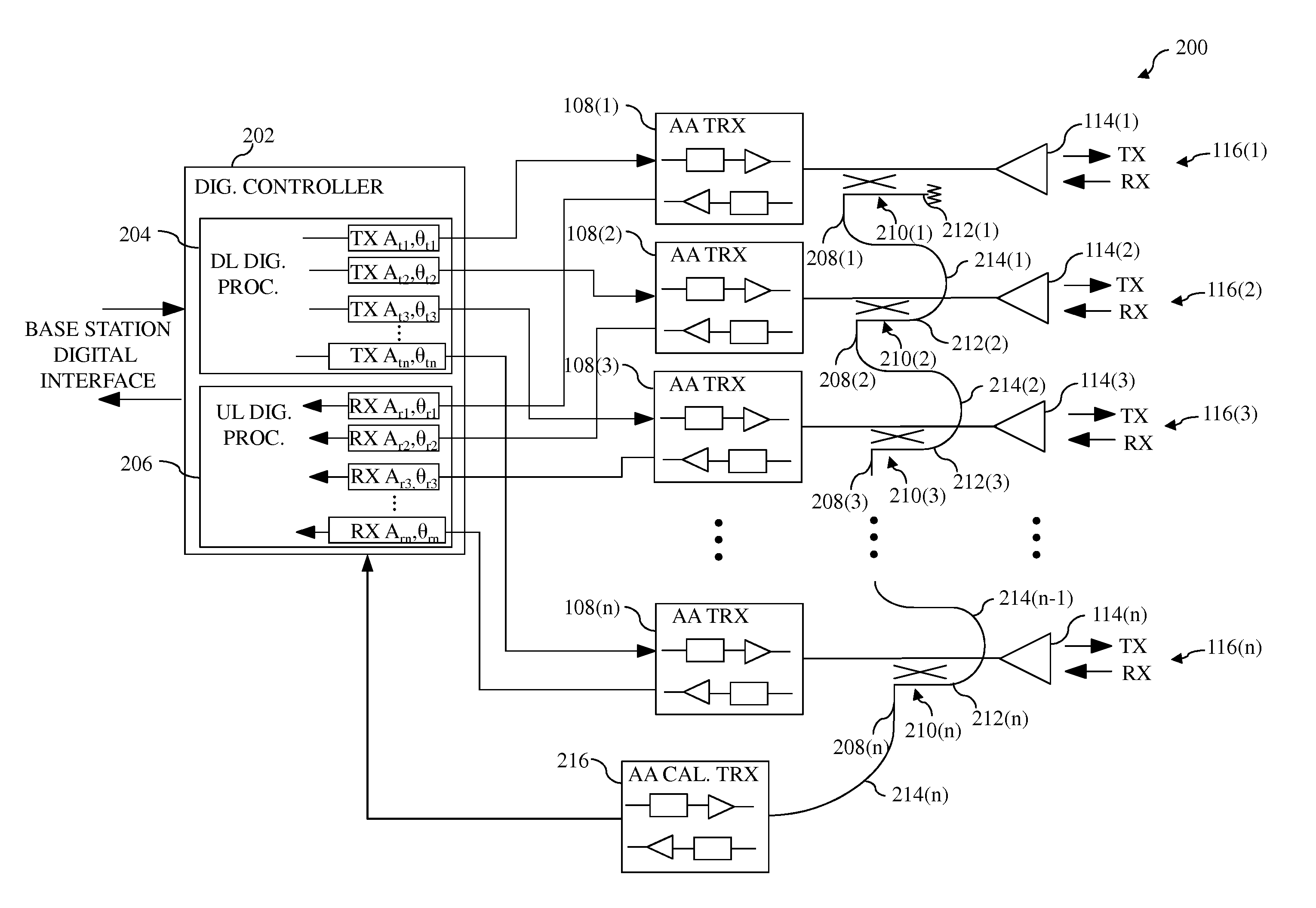
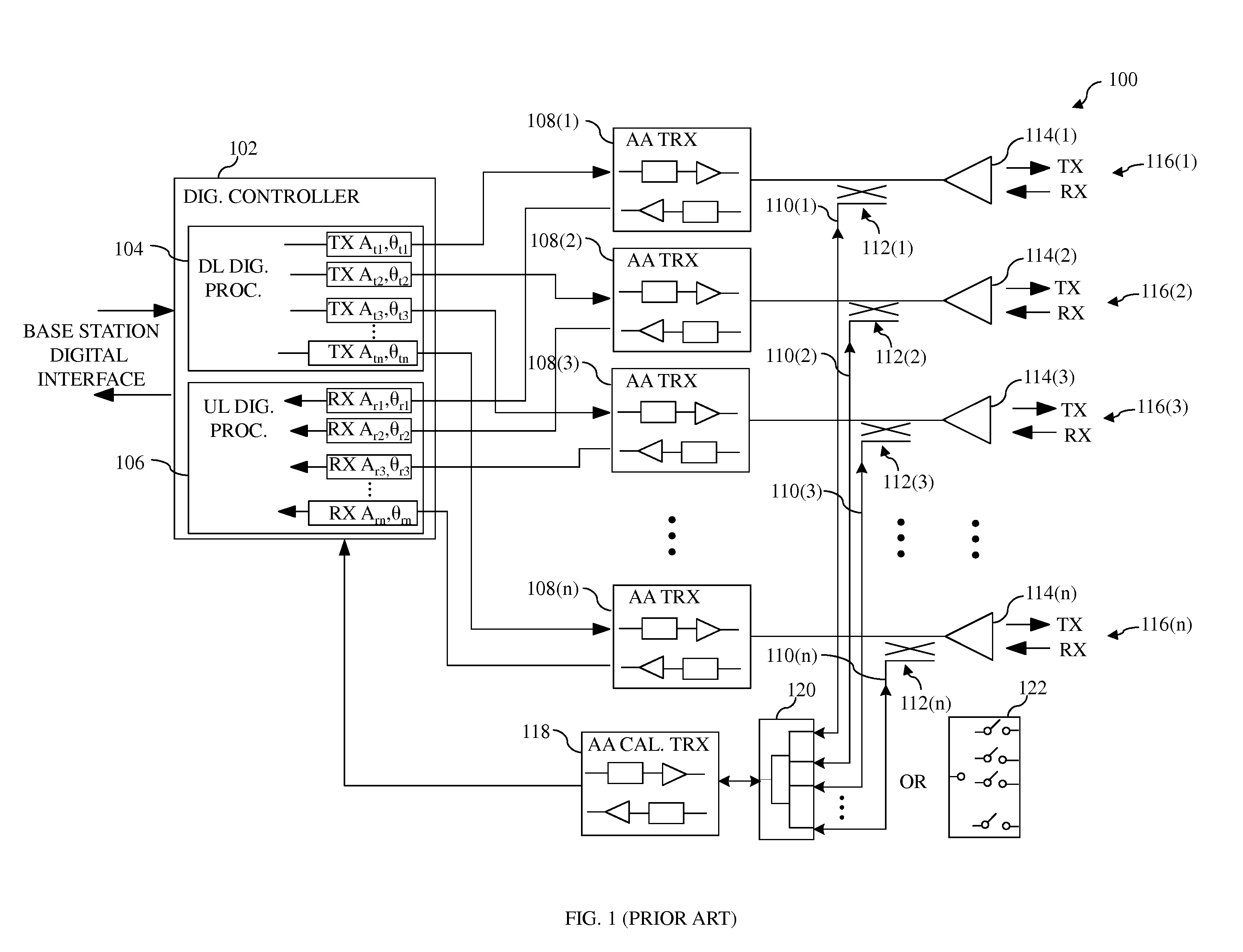
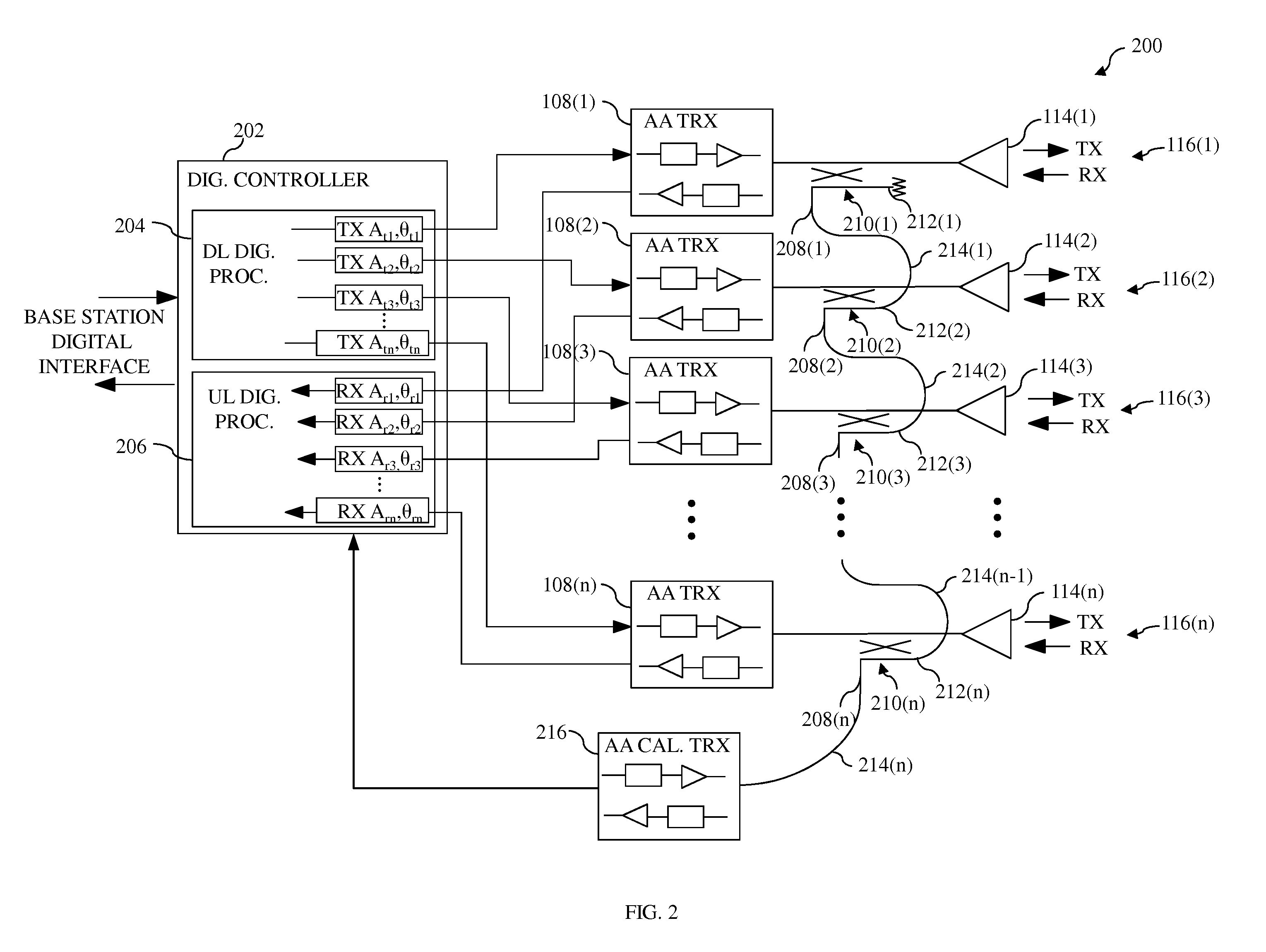
[0024]The calibration circuit of FIG. 1 includes a great deal of costly RF interconnection circuitry, namely combiner / splitter 120 (or RF switch matrix 122), directional couplers 112(1)-(n), and RF cables 110(1)-(n). Rather than implementing n RF cables 110(1)-(n) in a parallel-connected fashion such that each coupler 112(i) connects directly to combiner / splitter 120 as shown in FIG. 1, the couplers can be implemented in a series-connected fashion, such that the need for co...


PUM


Abstract

In one embodiment, an antenna system has a plurality of antenna paths and a calibration circuit. Each of the antenna paths has a transceiver and an antenna element. The calibration circuit has (i) a calibration transceiver and a different coupler coupled to each antenna path. The couplers are connected in series with one another and with the calibration transceiver. Connecting the couplers in series, rather than in parallel, reduces the amount of cabling needed and the need for a combiner/splitter or switch matrix between the couplers and the calibration transceiver, thereby reducing the cost, volume, and/or weight associated with the calibration circuit.

Description

CROSS-REFERENCE TO RELATED APPLICATIONS[0001]This application claims the benefit of the filing date of U.S. provisional application No. 61 / 616,696, filed on Mar. 28, 2012 as attorney docket no. 1052.102PROV, the teachings of all of which are incorporated herein by reference in their entirety.BACKGROUND OF THE INVENTION[0002]1. Field of the Invention[0003]The present invention relates to radio antenna systems, and, more specifically but not exclusively, to controlling radiation and reception patterns of radio antenna systems.[0004]2. Description of the Related Art[0005]FIG. 1 shows a simplified block diagram of one implementation of a prior-art cellular-radio antenna system 100. In general, radio antenna system 100 is a bi-directional system that operates concurrently in both a transmit direction (i.e., downlink direction) and a receive direction (i.e., uplink direction). Radio antenna system 100 comprises a plurality of active antenna paths 116, each path 116(i) comprising a transce...

Claims


Application Information

Patent Timeline
IPC IPC(8): H04M1/02
CPCH01Q1/246H01Q3/2605H04B17/12H04M1/026H04B17/0085H01Q3/267
Inventor RUCKI, JOHN S.VEIHL, JONATHON C.ROY, SANTANULY, TRUNG
Owner ANDREW LLC
Why Eureka
Try Eureka