Advanced kink resistant stent graft

a kink resistant, grafting technology, applied in the field of implantable devices, can solve the problems of relatively high morbidity and mortality rate of procedures for treating aortic aneurysms, generally regarded as involving higher risk and more difficulty

Active Publication Date: 2013-10-03
TRIVASCULAR2
View PDF6 Cites 40 Cited by
  • Summary
  • Abstract
  • Description
  • Claims
  • Application Information

AI Technical Summary

Benefits of technology

[0014]There may be provided a method of making a crimped stent graft, including the steps of: providing a tubular stent having an inner surface and an outer surface, the stent including an undulating wire having opposed first and second ends and being helically wound into a plurality of approximate circumferential windings to define a stent wall; the undulating wire having a plurality undulations defined by peaks and valleys with peaks of adjacent approximate circumferential windings being separated by a distance; axially stretching the tubular stent; disposing a graft liner on the inner surface of the axially stretched tubular stent, the graft liner including first plurality of layers of porous PTFE having no discernable node and fibril structure; disposing a graft covering on the outer surface of the axially stretched tubular stent, the graft covering including a second plurality of layers of porous PTFE having no discernable node and fibril structure; and allowing the axially stretched tubular stent to relax, forming crimps in the graft liner and the graft covering.

Problems solved by technology

Surgical procedures to treat aortic aneurysms can have relatively high morbidity and mortality rates due to the risk factors inherent to surgical repair of this disease as well as long hospital stays and painful recoveries.
This is especially true for surgical repair of TAAs, which is generally regarded as involving higher risk and more difficulty when compared to surgical repair of AAAs.

Method used


Image

  • Advanced kink resistant stent graft
  • Advanced kink resistant stent graft
  • Advanced kink resistant stent graft

Examples


embodiment 12

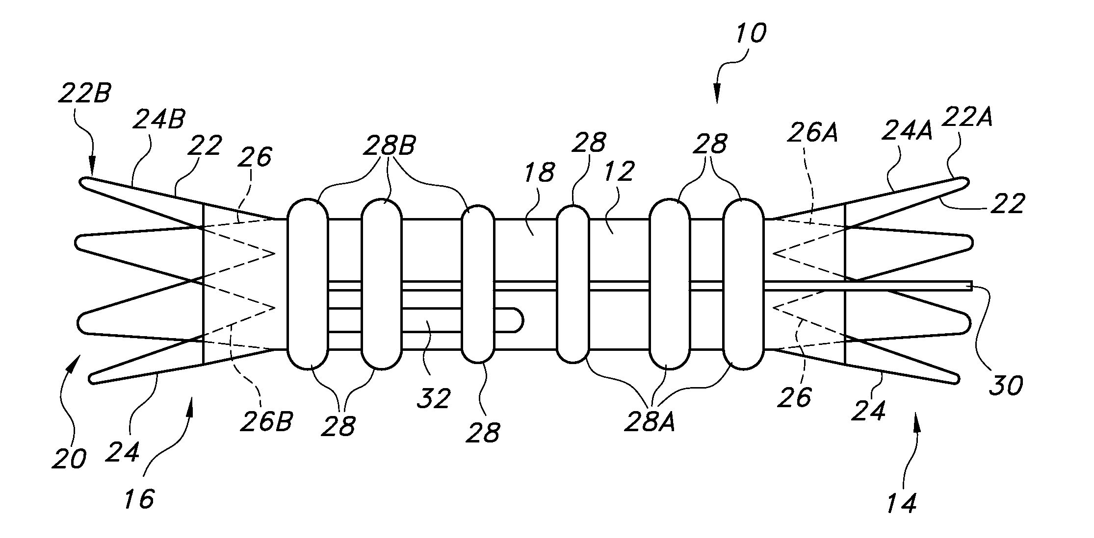
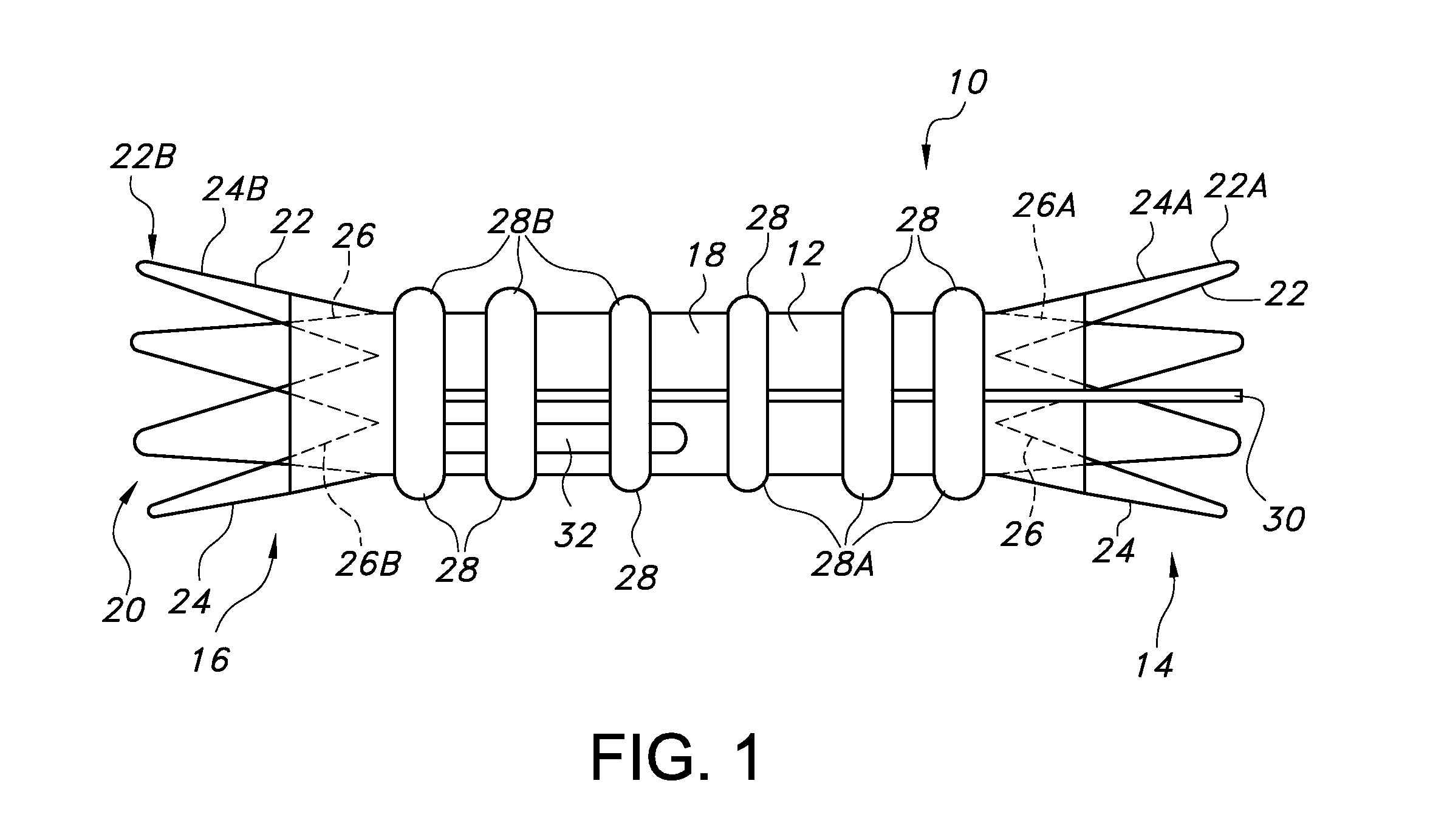
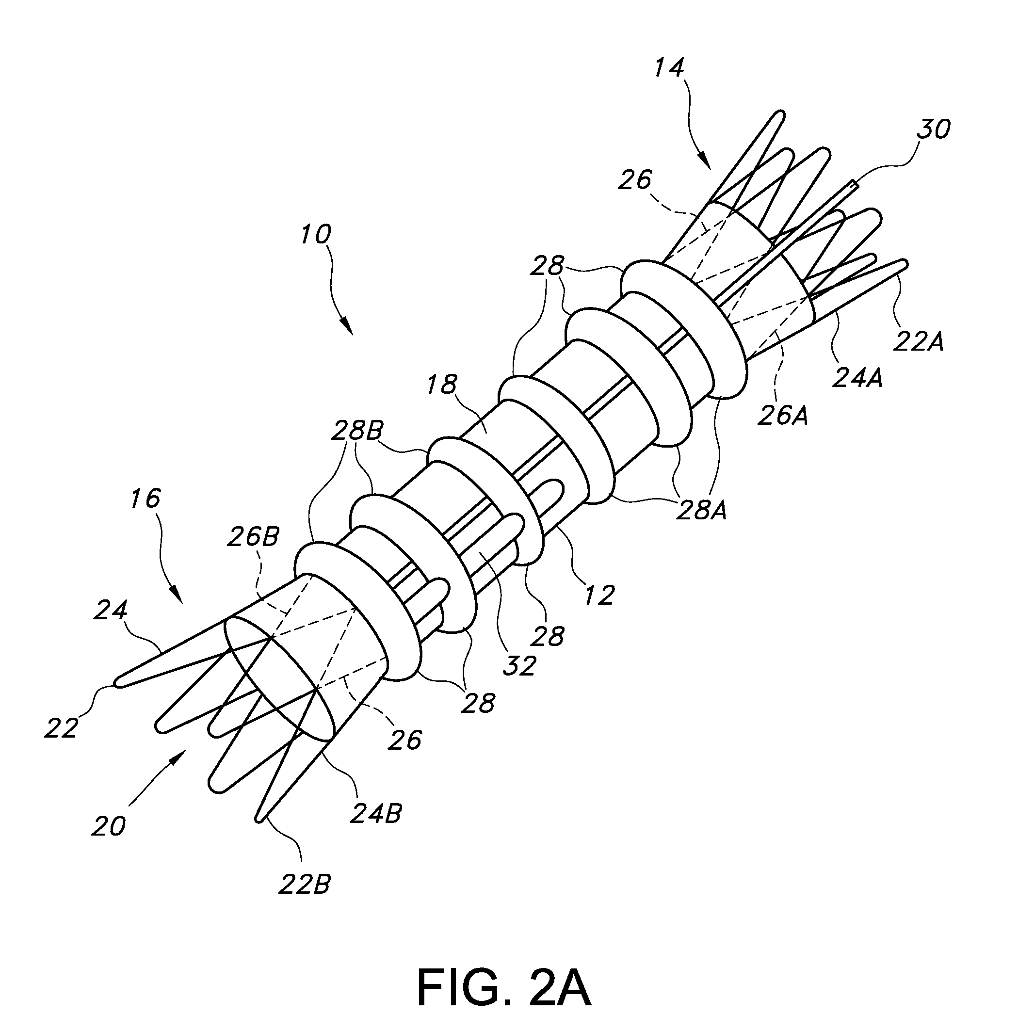
[0049]Some embodiments of main graft member 12 may include about 1 to about 8 circumferential inflatable channels disposed about the graft body 12. Some embodiments of the graft body 12 may include about 1 to about 4 longitudinal (or axial) inflatable fill channels 30 that may serve to connect the circumferential inflatable channels 28. Some embodiments of the circumferential channels 28 may extend a full circumference of the graft section upon which they are disposed, or they may extend only partially around the graft section upon which they are disposed. For the graft body embodiment 12 shown in FIGS. 1 and 2A, the network of inflatable channels 28 includes an inflatable cuff (28A) disposed adjacent the proximal end 14 of the main body portion of the graft body 12. A longitudinal or axial channel extends substantially along the graft body 12 in fluid communication with the circumferential channels 28 and proximal inflatable cuff 28A at the proximal end of the graft body 12. The lo...

embodiment 112

[0066]Some embodiments of main graft member 112 may include about 1 to about 8 circumferential inflatable channels 130,132 disposed about each leg 118, 120 and about 1 to about 8 proximal circumferential channels 128 disposed about a main body portion of the main graft member 112. Some embodiments of the main graft body member 112 may include about 1 to about 4 longitudinal or axial inflatable fill channels 134, 136 that may serve to connect the circumferential inflatable channels (128, 130, 132). Some embodiments of the circumferential channels may extend a full circumference of the graft section upon which they are disposed, or they may extend only partially around the graft section upon which they are disposed. For the main graft member embodiment 112 shown in FIG. 6, the network of proximal inflatable channels 128, 128′ includes an inflatable cuff 128′ disposed adjacent the proximal end 114 of the main body portion 112 and a circumferential channel 128 disposed just distal of th...

embodiment 110

[0092]It may be useful for some embodiments of the main graft 112 to have a nominal axial length which is configured to allow the use of the main graft 112 in a wide variety of vascular morphologies with supplementation by one or more graft extensions 142 and 144. A modular graft embodiment 110 is normally chosen in order to have a proper fit to the patient's vasculature. For some graft indications, it is necessary to produce a large number of size variations of the graft system, or graft assembly 110 components, in order to accommodate the size and configuration variations of each patient's vasculature in order to achieve an acceptable fit of the graft assembly 110 within the patient's vasculature. This can be very costly and time consuming for the manufacturer of the endovascular graft assembly 110 and the hospitals which must maintain a comprehensive inventory of the devices. In addition, this may require an inconvenient amount of shelf space in the hospital operating room or cat...


PUM

PropertyMeasurementUnit
winding angleaaaaaaaaaa
axial lengthaaaaaaaaaa

Abstract

Stent-grafts for treating thoracic aortic aneurysms and abdominal aortic aneurysms include graft portions having inflatable channels and graft extensions. The graft extensions include an undulating wire stent and porous, but substantially fluid impermeable, polytetrafluoroethylene (PTFE) graft materials.

Description

CROSS-REFERENCE TO RELATED APPLICATIONS[0001]This application claims the benefit of U.S. Provisional Application No. 61 / 619,715, filed Apr. 3, 2012, the contents of which are incorporated herein by reference.FIELD OF THE INVENTION[0002]The present invention relates to implantable devices for treating diseased bodily lumens. More particularly, the present invention relates to stent-grafts for treating thoracic aortic aneurysms and abdominal aortic aneurysms.BACKGROUND[0003]An aneurysm is a medical condition indicated generally by an expansion and weakening of the wall of an artery of a patient. Aneurysms can develop at various sites within a patient's body. Thoracic aortic aneurysms (TAAs) or abdominal aortic aneurysms (AAAs) are manifested by an expansion and weakening of the aorta which is a serious and life threatening condition for which intervention is generally indicated. Existing methods of treating aneurysms include invasive surgical procedures with graft replacement of the a...

Claims


Application Information

Patent Timeline
Patent Type & Authority Applications(United States)
IPC IPC(8): A61F2/06
CPCA61F2/07Y10T29/49927A61F2002/91516A61F2002/91541A61F2230/0078A61F2250/0003A61F2/88A61F2/89A61F2002/065A61F2002/067A61F2002/072A61F2002/825A61L31/048A61L31/146A61F2/06C08L27/18A61F2240/001
Inventor YOUNG, SARAHLI, CHENGCHOBOTOV, MICHAEL V.STEPHENS, PATRICKWHIRLEY, ROBERT G.
Owner TRIVASCULAR2
Why Eureka
Try Eureka