

Imaging lens
a technology of imaging lenses and occlusion, applied in the field of imaging lenses, can solve the problems of weak power of the first lens, disadvantageous in order to achieve thinness, and insufficient brightness of the imaging lens, so as to shorten the total track length, and achieve mass production
- Summary
- Abstract
- Description
- Claims
- Application Information
AI Technical Summary
Benefits of technology
Problems solved by technology
Method used
Image

Examples
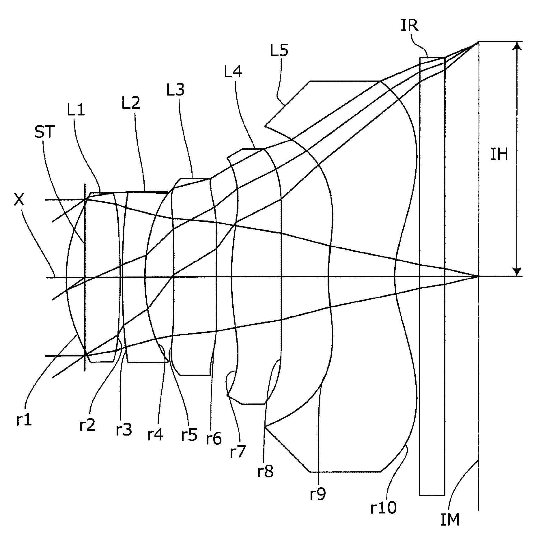
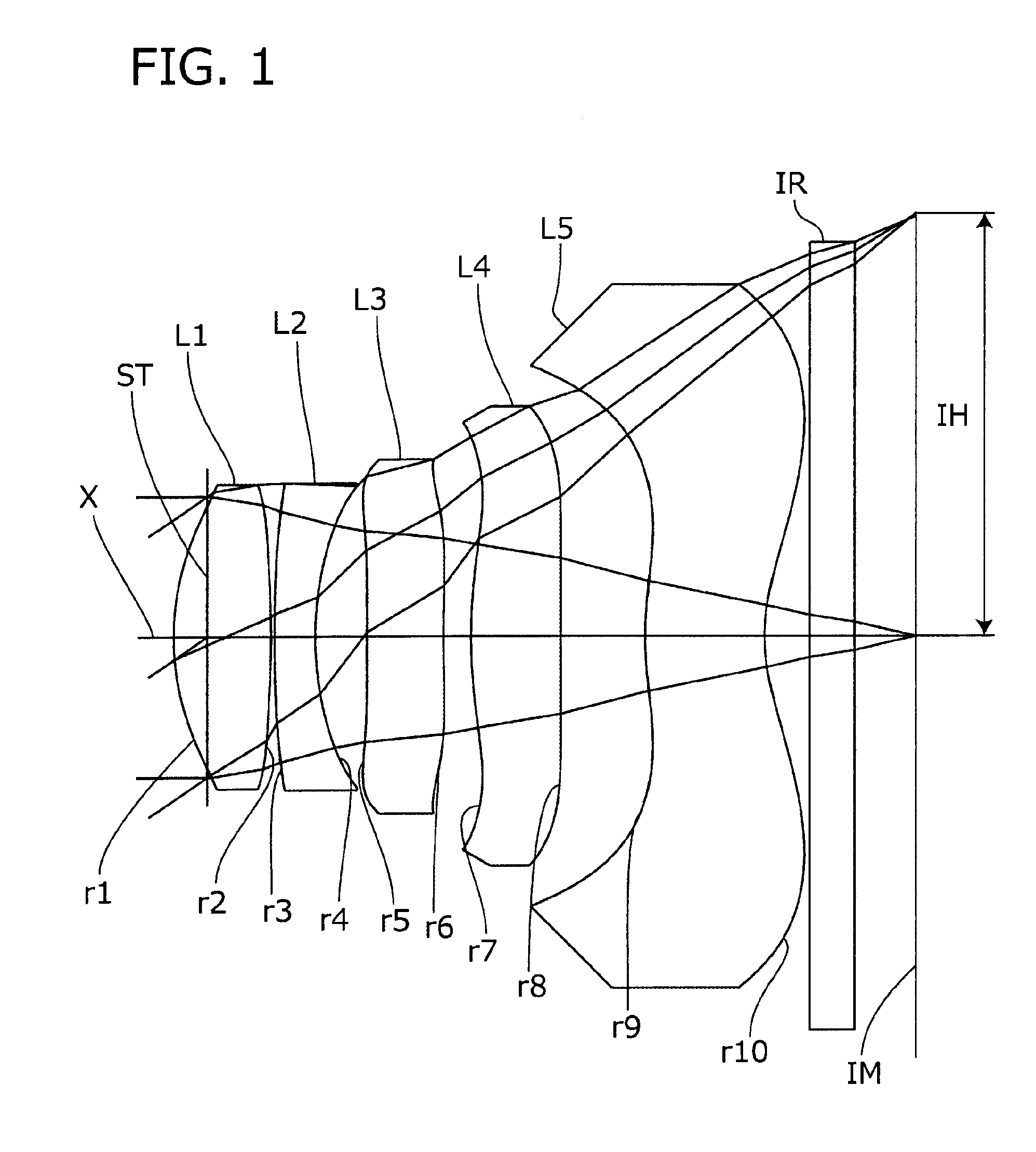
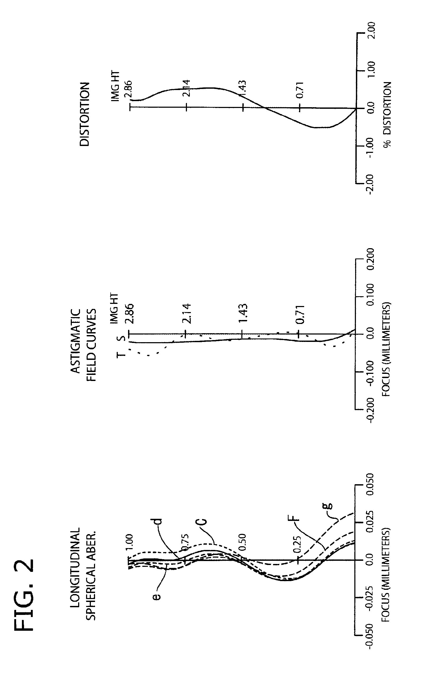
embodiment 1
[0073]The basic lens data of the Embodiment 1 is shown below in Table 1.
TABLE 1Unit mmf = 4.160Fno = 2.20ω(°) = 34.49IH = 2.856Surface dataSurfaceCurvatureSurfaceRefractiveAbbe No.No. iradius rdistance dindex Ndνd(Object surface)InfinityInfinityStopInfinity−0.2251*1.7540.6551.53556.162*−5.2590.0253*18.1750.2701.63523.914*2.1110.3505*49.6670.5161.53556.166*9.9710.1877*3.4790.6051.53556.168*21.7780.5739*2.4020.8001.53556.1610* 1.3340.311 Infinity0.31.51764.2012 Infinity0.607Image planeInfinitySingle lens dataLensStart planeFocal length112.53323−3.74635−23.343477.62459−7.565Aspheric dataFirstSecondThirdFourthFifthsurfacesurfacesurfacesurfacesurfacek−1.898E+00−1.818E+00 0.000E+00−2.723E−01 0.000E+00A4 3.822E−02 1.288E−01 4.814E−02−8.944E−02−1.060E−01A6−2.809E−02−1.343E−01 6.037E−02 2.532E−01 5.779E−02A8 4.970E−02 1.978E−02−1.838E−01−3.068E−01 1.251E−03A10−5.149E−02 3.399E−04 1.217E−01 2.175E−01−3.017E−02A12 4.628E−03−6.173E−04−1.665E−02−5.539E−02 6.065E−02A14 4.215E−03−5.735E−04−5.234E−...
embodiment 2
[0077]The basic lens data of the Embodiment 2 is shown below in Table 2.
TABLE 2Unit mmf = 4.159Fno = 2.20ω(°) = 34.50IH = 2.856Surface dataSurfaceCurvatureSurfaceRefractiveAbbe No.No. iradius rdistance dindex Ndνd(Object surface)InfinityInfinityStopInfinity−0.2251*1.8740.5841.53556.162*−21.9650.1003*33.4380.2601.63523.914*2.3430.2385*3.8660.6101.53556.166*11.0670.3867*4.1330.5051.53556.168*41.2700.4609*2.3150.7231.53556.1610* 1.2610.411 Infinity0.31.51764.2012 Infinity0.486Image planeInfinitySingle lens dataLensStart planeFocal length113.24423−3.9393510.749478.51559−6.788Aspheric dataFirstSecondThirdFourthFifthsurfacesurfacesurfacesurfacesurfacek−1.886E+004.388E+023.059E−02−1.458E+00 0.000E+00A4 3.969E−021.085E−013.059E−02−1.085E−01 −1.362E−01A6−2.319E−02−1.011E−01 3.157E−022.070E−01 3.780E−02A8 5.384E−022.255E−02−1.821E−01 −3.220E−01 4.319E−03A10−4.879E−02−1.427E−02 1.166E−012.360E−01−2.479E−02A12 3.911E−03−2.987E−03 −1.491E−02 −5.626E−02 6.121E−02A14 5.711E−034.239E−031.644E−03...
embodiment 3
[0081]The basic lens data of the Embodiment 3 is shown below in Table 3.
TABLE 3Unit mmf = 4.142Fno = 2.20ω(°) = 34.75IH = 2.856Surface dataSurfaceCurvatureSurfaceRefractiveAbbe No.No. iradius rdistance dindex Ndνd(Object surface)InfinityInfinityStopInfinity−0.2001*1.8720.5911.53556.162*−5.5480.0473*6.3550.2761.63523.914*1.7100.4585*8.5000.3921.53556.166*9.6000.3387*7.5280.5231.53556.168*736.7530.2489*1.9730.8481.53556.1610* 1.5090.411 Infinity0.31.51764.2012 Infinity0.600Image planeInfinitySingle lens dataLensStart planeFocal length112.68223−3.73335122.8794714.16459−33.034Aspheric dataFirstSecondThirdFourthFifthsurfacesurfacesurfacesurfacesurfacek−2.217E+00 0.000E+000.000E+00−9.585E−01 0.000E+00A43.626E−021.141E−012.186E−02−9.693E−02 −1.324E−01 A6−2.837E−02 −1.313E−01 5.007E−022.423E−015.992E−02A83.465E−024.347E−02−1.746E−01 −3.158E−01 3.496E−03A10−3.540E−02 −1.263E−02 1.461E−012.226E−01−3.148E−02 A120.000E+000.000E+00−3.230E−02 −5.368E−02 5.376E−02A140.000E+000.000E+000.000E+000.00...
PUM
 Abstract
Description
Claims
Application Information