Apparatus and method for aligning visible light communication devices in visible light communication system

Active Publication Date: 2013-10-10
SAMSUNG ELECTRONICS CO LTD
View PDF9 Cites 25 Cited by
  • Summary
  • Abstract
  • Description
  • Claims
  • Application Information

AI Technical Summary

Benefits of technology

The present invention is a solution to problems in visual light communication systems where devices may become too far out to be easily identified. The invention uses a camera and screen to accurately align the communication link, even if the light signal is too weak. This makes it easier for users to identify and connect with each other.

Problems solved by technology

However, as the distance between two devices attempting to communicate with each other increases, the visibility is deteriorated.
However, such a power increase naturally causes incidental increase of power consumption.
Further, an increase in the power of the signal may cause the devices themselves to generate heat.
Moreover, the brightness of the light source may be increased so much that the light source may act as an obstruction to other peripheral devices or the user.

Method used


Image

  • Apparatus and method for aligning visible light communication devices in visible light communication system
  • Apparatus and method for aligning visible light communication devices in visible light communication system
  • Apparatus and method for aligning visible light communication devices in visible light communication system

Examples


Embodiment Construction

[0026]Hereinafter, various embodiments of the present invention will be described with reference to the accompanying drawings. In the following description, the same elements will be designated by the same reference numerals although they are shown in different drawings. Further, various specific definitions found in the following description are provided only to help general understanding of the present invention, and it is apparent to those skilled in the art that the present invention can be implemented without such definitions. Further, in the following description of the present invention, a detailed description of known functions and configurations incorporated herein will be omitted when it may make the subject matter of the present invention rather unclear.

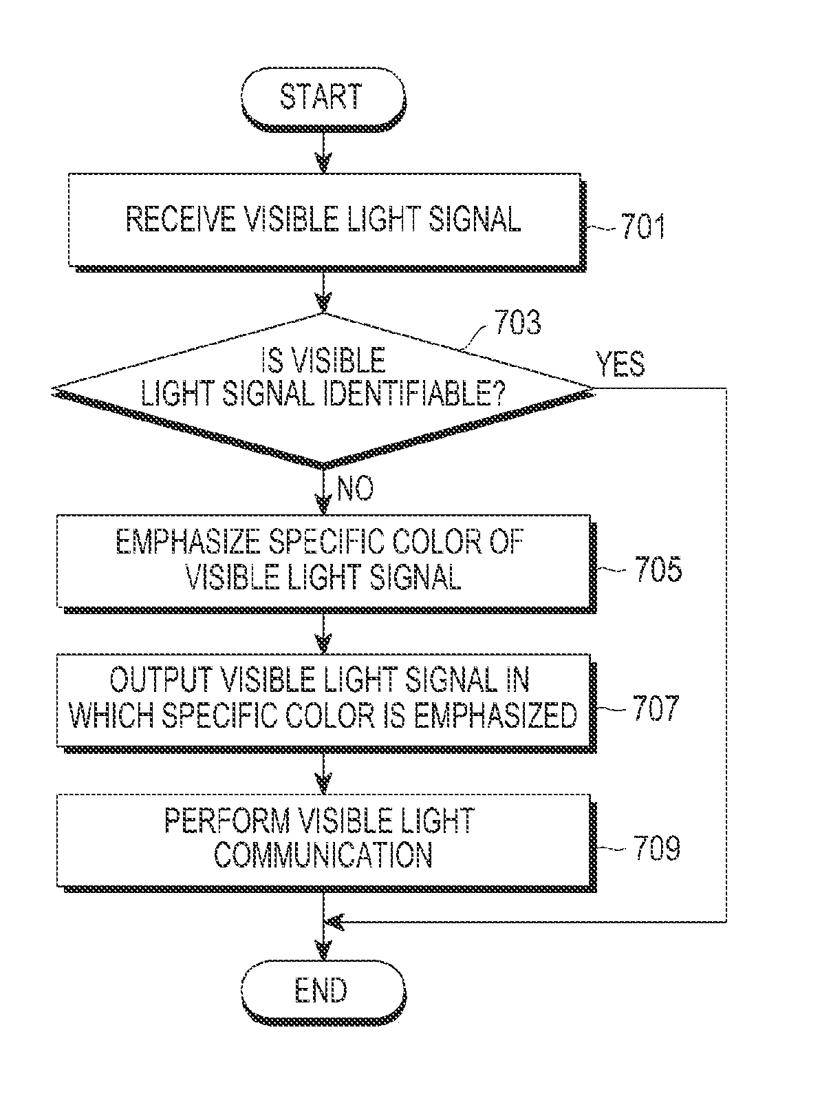
[0027]The present invention proposes a method for making a received visible light signal more clearly shown, by using a camera and a screen mounted to a visible light communication device in a visible light communication s...


PUM


Abstract

A method for aligning among visible light communication devices comprises the following steps: generating a visible light signal and transmitting same to a corresponding device; determining whether the visible light signal that is output via the screen of the device is identifiable; correcting the color of the visible light signal that is output on the screen if the visible light signal is not identifiable; and using the visible light signal that is corrected to perform alignment for visible light communicating with the corresponding device.

Description

BACKGROUND OF THE INVENTION[0001]1. Field of the Invention[0002]The present invention relates to visible light communication, and more particularly, to an apparatus and a method for aligning visible light communication devices by using a camera and a screen mounted to a mobile terminal.[0003]2. Description of the Related Art[0004]In general, visible light communication refers to a wireless communication technology using light in a visible wavelength range, and in recent years, studies on the visible light communication have been increasingly conducted along with proliferation of a light emitting diode (LED). Recently, the visible light communication mainly using the LED as a light source for communication has been more spotlighted due to lack of frequencies in a radio frequency (RF) band, a possibility of cross talk between various wireless communication technologies, and an increased demand for communication security.[0005]In the general visible light communication, a transmitter e...

Claims


Application Information

Patent Timeline
IPC IPC(8): H04B10/112H04B10/116
CPCH04B10/112H04B10/116H04B10/1149
Inventor BAE, TAE-HANSON, JAE-SEUNGWON, EUN-TAE
Owner SAMSUNG ELECTRONICS CO LTD
Why Eureka
Try Eureka