Devices and methods for accessing a cerebral vessel

a technology for removing obstructions and cerebral vessels, applied in blood vessels, medical science, surgery, etc., can solve problems such as rigidity of typical guide catheters, and achieve the effect of optimizing advancement and support and more effective transmission of for

Inactive Publication Date: 2013-10-10
STRYKER CORP
View PDF5 Cites 59 Cited by
  • Summary
  • Abstract
  • Description
  • Claims
  • Application Information

AI Technical Summary

Benefits of technology

[0005]In one aspect of the present invention, a support catheter is provided which can be advanced over an obstruction retrieval device and guided into the proximal portion of the MCA. Positioning the support catheter in the MCA at a position close to the retriever can provide a more effective transmission of force to the retriever. Positioning the support catheter in this manner may also provide a more axially oriented force than would be provided if the support catheter were not able to navigate to the MCA. Typical guide catheters, for example, are too stiff to navigate the tight bends and tortuosity of the distal ICA and the siphon. The support catheter of the present invention, on the other hand, is flexible enough to navigate the distal ICA and the siphon. The support catheter may also be large enough to allow for a microcatheter to be positioned between the support catheter and the retriever. The proximal portion of the support catheter may be somewhat stiff and rigid for optimized advancement and support.
[0007]The microcatheter is advanced through the guide catheter and into or distal to the obstruction. Withdrawal of the microcatheter exposes a portion of the retriever, which is now in contact with the obstruction. If the retriever is deployed distal to the obstruction, the microcatheter and retriever are withdrawn together until the retriever engages the obstruction. The end of the support catheter is advanced to a position near the obstruction to provide the advantages described herein. The retriever may then be pulled proximally to dislodge and remove the obstruction. By advancing the support catheter nearer to the obstruction and retriever than would be possible with typical guide catheters, the problems concerning vessel compression and collapse discussed above may be reduced or avoided since the support catheter will provide a more axially directed force relative to the vessel. Another advantage of positioning the support catheter just proximal to the obstruction is that suction can be applied to the lumen of the support catheter to assist in removal of the obstruction.

Problems solved by technology

Typical guide catheters, for example, are too stiff to navigate the tight bends and tortuosity of the distal ICA and the siphon.

Method used


Image

  • Devices and methods for accessing a cerebral vessel
  • Devices and methods for accessing a cerebral vessel
  • Devices and methods for accessing a cerebral vessel

Examples


Embodiment Construction

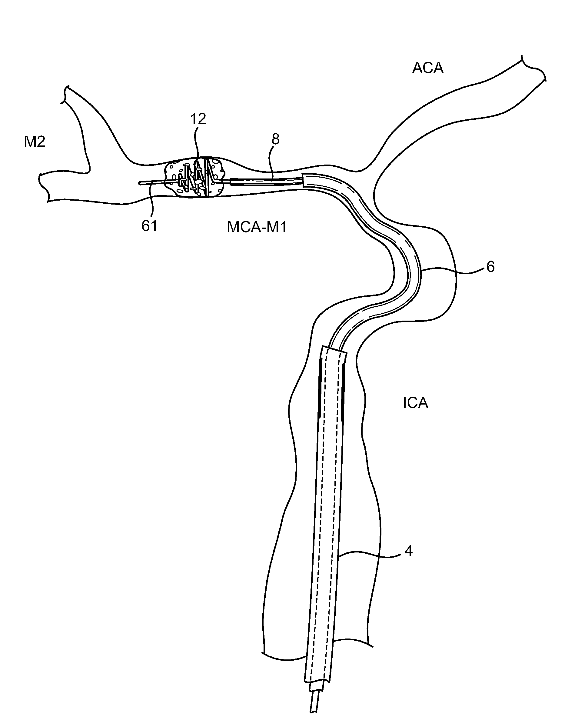
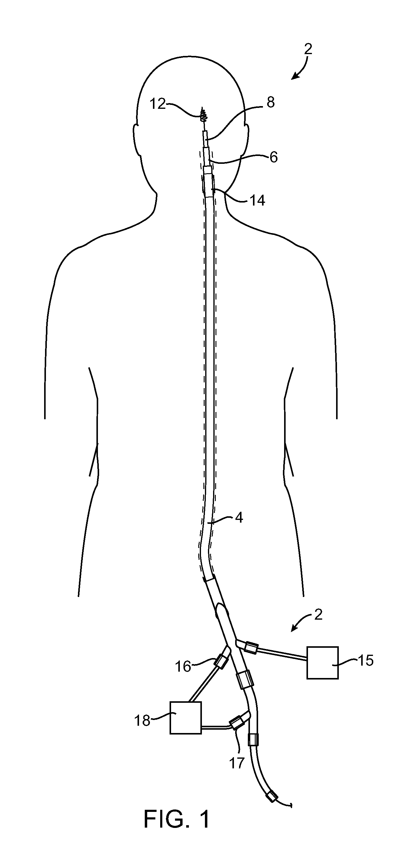
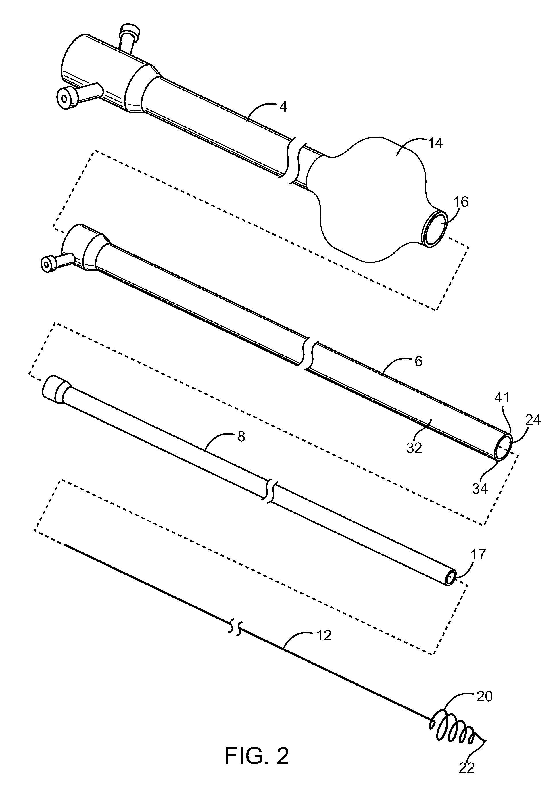
[0014]Referring to FIG. 1, a system 2 for removing an obstruction from a vascular location is shown. The system 2 is particularly useful for removing obstructions from the cerebral vasculature. The system 2 includes a guide catheter 4, a support catheter 6, a microcatheter 8, a guidewire and an obstruction retriever 12. The guide catheter 4 is advanced within the vasculature and guides the other catheters and devices through the larger vessels leading to the obstruction. The guide catheter 4 may have a balloon 14 which is coupled to a source of inflation fluid 15 and is inflated during the procedure to temporarily stop blood flow when removing the obstruction. The guide catheter 4 may have a lumen 16 and the support catheter 6 may have a lumen 17 which both may be coupled to a vacuum source 18 for aspirating the obstruction. Of course, the present invention may be practiced with one or more of the catheters without departing from various aspects of the invention. For example, the su...


PUM


Abstract

The present invention is directed to methods and devices for accessing a cerebral vessel. The system includes a support catheter, which can be advanced into small and tortuous vessels. By advancing the support catheter nearer to the obstruction then can be achieved with conventional guide catheters, the support catheter reduces the likelihood vessel compression and collapse when manipulating a working catheter.

Description

CROSS-REFERENCE TO RELATED APPLICATIONS[0001]The present application is a continuation in part of U.S. patent application Ser. No. 11 / 490,843, filed Jul. 21, 2006, which is incorporated herein by reference.BACKGROUND OF THE INVENTION[0002]The present invention is directed to devices and methods for removing obstructions from a cerebral vessel. In particular, the present invention may be useful in removing obstructions from the M1 or M2 Middle Cerebral Artery (MCA). Of course, the present invention may find uses in other parts of the cerebral vasculature and in other parts of the body.[0003]Various problems can occur when attempting to remove hard, well organized and / or impacted clots or obstructions with a retrieval device in the Middle Cerebral Artery. Vessel compression and displacement can occur in the soft, flexible and relatively unsupported cerebral vasculature when force is applied to the clot and the retriever to dislodge the clot. For example, the proximal portion of the MC...

Claims


Application Information

Patent Timeline
Patent Type & Authority Applications(United States)
IPC IPC(8): A61B17/22A61F2/95
CPCA61B2017/22034A61B2017/2217A61F2/95A61B17/22A61B17/221
Inventor WILSON, SCOTTMILLER, JOHNVU, EMILY
Owner STRYKER CORP
Why Eureka
Try Eureka