Method and apparatus for determining the 3D coordinates of an object

a technology of 3d coordinates and methods, applied in the direction of instruments, electrical devices, measurement devices, etc., can solve the problem of insufficient accuracy of methods, and achieve the effect of saving measurement tim

Inactive Publication Date: 2013-10-17
CARL ZEISS OPTOTECHN GMBH
View PDF23 Cites 10 Cited by
  • Summary
  • Abstract
  • Description
  • Claims
  • Application Information

AI Technical Summary

Benefits of technology

[0020]The invention also provides for supplementing an existing apparatus for determining the 3D coordinates of an object according to the generic part of claim 8 in a simple way, in order to be able to determine the 3D coordinates of an object which is larger than the field of view of the camera with this apparatus. Furthermore, it is possible to provide several cameras. For example, a so-called stereo camera can be used, i.e. a combination of two cameras. It is, however, also possible to provide more than two cameras. By using more than one camera, the allocation of the image points recorded by the cameras to the projected lines can be improved.
[0026]It may be advantageous when the 3D coordinates of an object are determined on the basis of stored positions of the reference marks. This is advantageous in particular when in a first measurement run the positions of the reference marks are detected and possibly transformed and stored. It is, however, also possible to determine the 3D coordinates of an object on the basis of positions of the reference marks which have already been stored. By using the stored positions of the reference marks, measurement time can be saved. It may, however, also be advantageous to newly determine the positions of the reference marks during a or each determination of the 3D coordinates of an object.

Problems solved by technology

However, with larger objects with little surface structure, the method possibly is not sufficiently accurate.

Method used


Image

  • Method and apparatus for determining the 3D coordinates of an object
  • Method and apparatus for determining the 3D coordinates of an object
  • Method and apparatus for determining the 3D coordinates of an object

Examples


Embodiment Construction

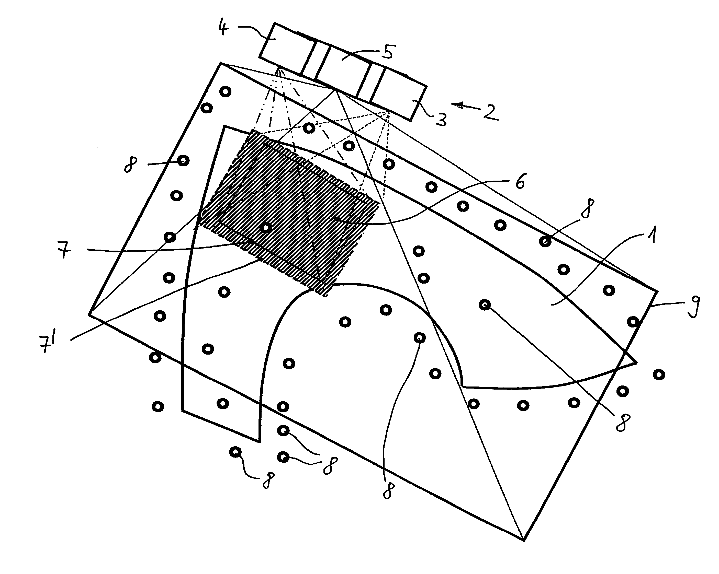
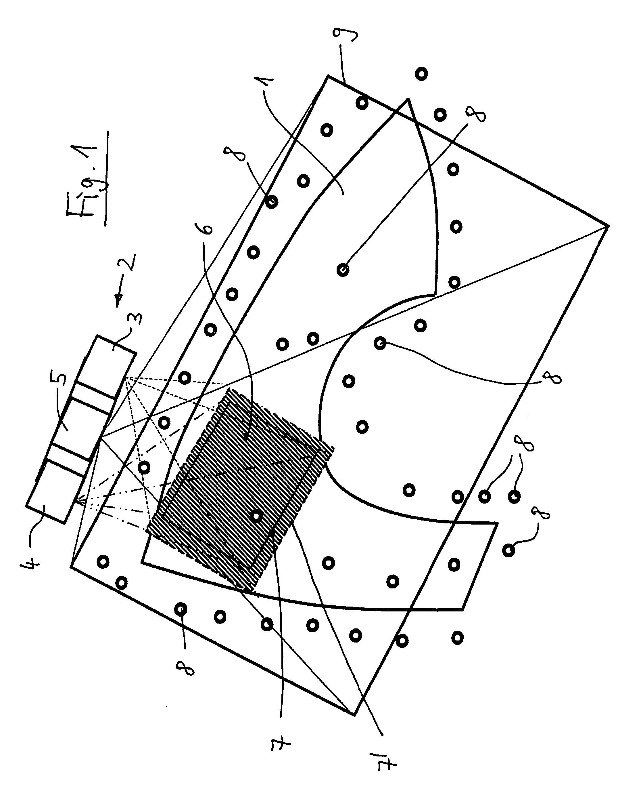
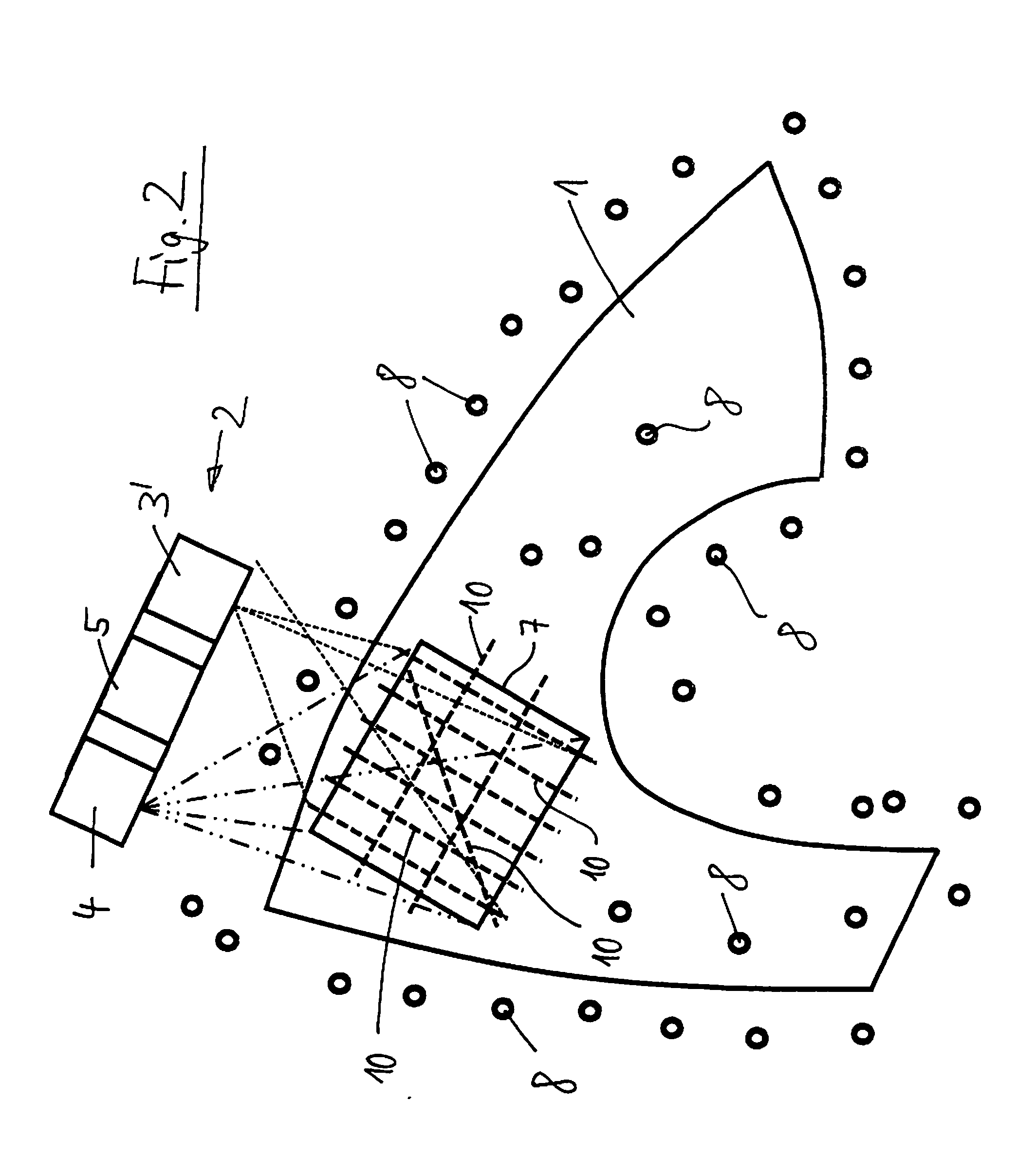
[0031]FIG. 1 shows an apparatus for determining the 3D coordinates of an object 1, namely a fender of a motor vehicle. The apparatus comprises a 3D sensor 2 which comprises a projector 3 and a camera 4. The apparatus furthermore comprises a reference camera 5 which is connected with the 3D sensor 2. In the exemplary embodiment, the reference camera 5 is located between the projector 3 and the camera 4.

[0032]A pattern, namely a stripe pattern 6, is projected onto the object 1 by the projector 3. The light reflected by the object 1 in the region of the stripe pattern 6 is captured by the camera 4.

[0033]The shot of the camera 4 is forwarded to an evaluating means (not shown in the drawing), by which it is evaluated. From the shot, the 3D coordinates of the object 1 can be determined in the field of view 7 of the camera 4. The contour 7′ of the stripe pattern 6 is larger than the field of view 7 of the camera 4. The contour 7′ encloses the field of view 7 on all sides. The camera 4 incl...


PUM


Abstract

In a method for determining the 3D coordinates of an object a pattern (6) is projected onto the object (1) by a projector (3), the light reflected by the object (1) is captured by a camera (4), and the shots recorded by the camera (4) are evaluated. Reference marks (8) on and / or beside the object (1) are recorded by a reference camera (5). The reference camera (5) has a larger field of view (9) than the camera (4). To improve such method, the reference camera (5) is connected with the camera (4) or with a 3D sensor (2) which comprises the projector (3) and the camera (4).

Description

BACKGROUND OF THE INVENTION[0001]This invention relates to a method for determining the 3D coordinates of an object and to an apparatus for carrying out such method.[0002]In the method, a pattern is projected onto the object. The light reflected by the object is captured and evaluated. The apparatus for carrying out such method comprises a projector for projecting a pattern onto the object, a camera for recording the object, and an evaluating means for evaluating the shots recorded.[0003]Methods and apparatuses of this kind are known already, for example from DE 10 2006 048 234 A1 and DE 10 2007 042 963 A1. In these methods, a stripe pattern can be projected onto the object. Usually, the stripe pattern is projected onto the object by the method of white-light stripe projection, i.e. with white light.[0004]As for determining the 3D coordinates of the object a single shot generally is not sufficient to satisfy the measurement requirements and / or to completely cover the object, it is r...

Claims


Application Information

Patent Timeline
Patent Type & Authority Applications(United States)
IPC IPC(8): H04N13/02
CPCH04N13/0203G01B11/2513H04N13/204
Inventor STEINBICHLER, MARCUSDAXAUER, HERBERTMAYER, THOMAS
Owner CARL ZEISS OPTOTECHN GMBH
Why Eureka
Try Eureka