Eureka AIR delivers breakthrough ideas for toughest innovation challenges, trusted by R&D personnel around the world.

Turbomachine blade tip shroud with parallel casing configuration

Active Publication Date: 2013-10-17
GENERAL ELECTRIC CO
View PDF15 Cites 12 Cited by
  • Summary
  • Abstract
  • Description
  • Claims
  • Application Information

AI Technical Summary

Benefits of technology

The invention is related to a turbomachine with a blade and a stationary structural component, which are connected together. The blade has a tip shroud with a leading edge that faces the structural component, which has a corresponding surface. The tips of the blade and the structural component have parallel contours, which results in a more precise connection between the two components. This design allows for better cooling and reduces the chance of damage during operation. The technical effects of the invention include improved efficiency and durability of the turbomachine.

Problems solved by technology

Existing tip shroud and seal design may not adequately limit or reduce flow leakage between the turbomachine blades and the stationary structural component surrounding the turbomachine blades and the rotor, which may result in a reduction in turbomachine efficiency.
Similarly, existing stationary structural component design may not adequately limit or reduce flow leakage between the turbomachine blades and the stationary structural component surrounding the turbomachine blades and the rotor.

Method used


Image

  • Turbomachine blade tip shroud with parallel casing configuration
  • Turbomachine blade tip shroud with parallel casing configuration
  • Turbomachine blade tip shroud with parallel casing configuration

Examples


Embodiment Construction

[0014]One or more specific embodiments of the present invention will be described below. In an effort to provide a concise description of these embodiments, all features of an actual implementation may not be described in the specification. It should be appreciated that in the development of any such actual implementation, as in any engineering or design project, numerous implementation-specific decisions must be made to achieve the developers' specific goals, such as compliance with system-related and business-related constraints, which may vary from one implementation to another. Moreover, it should be appreciated that such a development effort might be complex and time consuming, but would nevertheless be a routine undertaking of design, fabrication, and manufacture for those of ordinary skill having the benefit of this disclosure.

[0015]When introducing elements of various embodiments of the present invention, the articles “a,”“an,”“the,” and “said” are intended to mean that ther...


PUM


Abstract

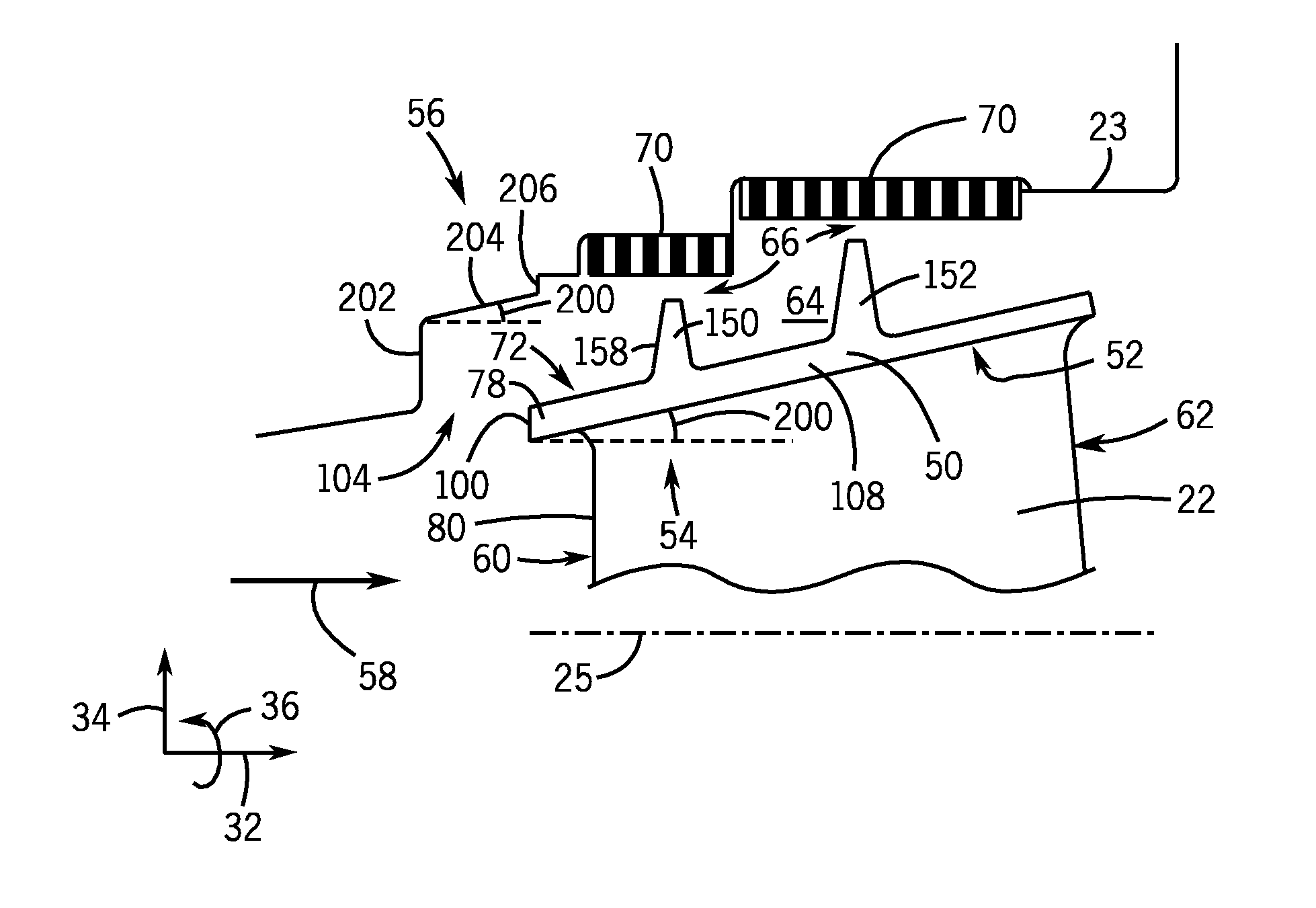
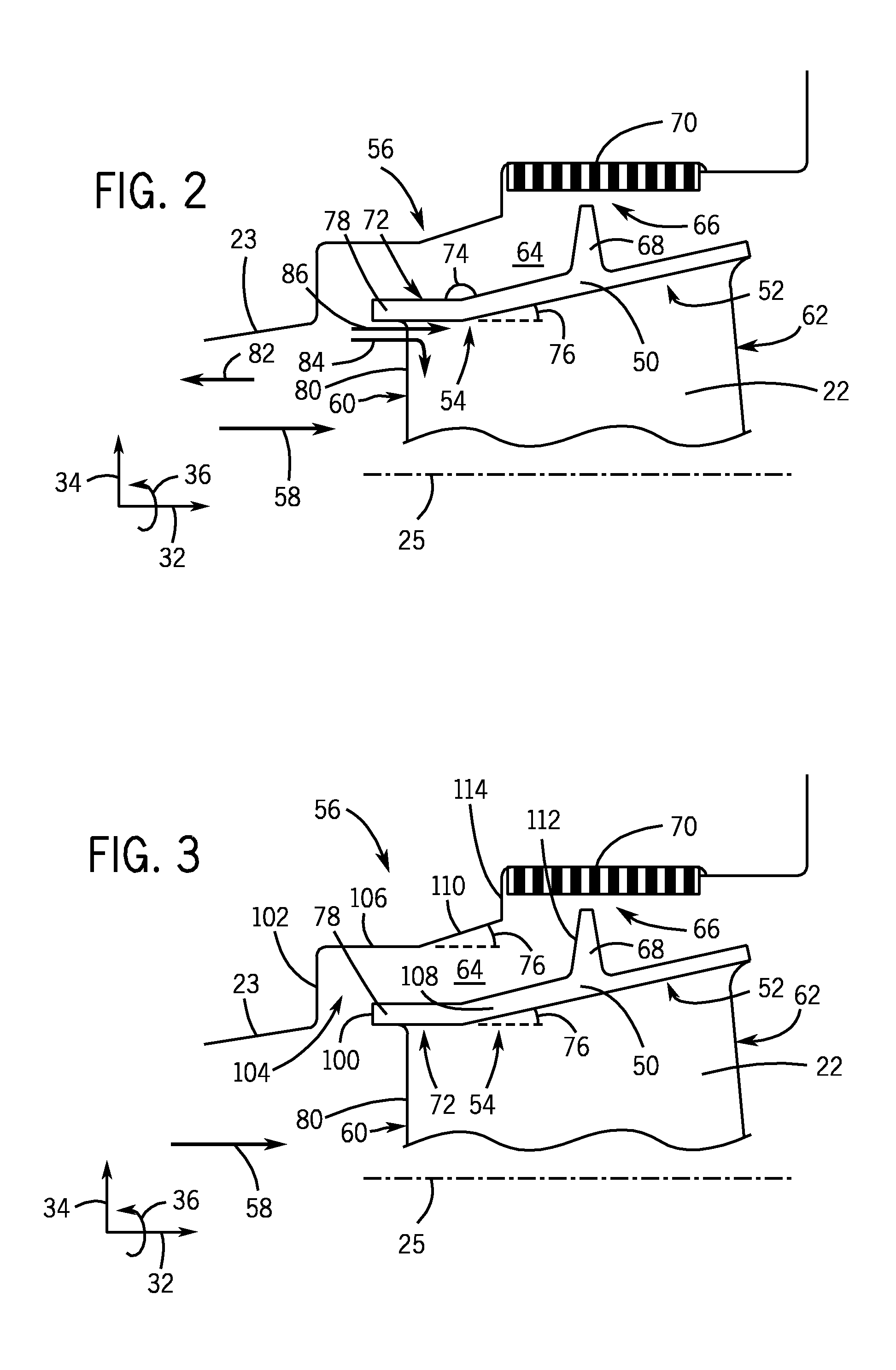
Embodiments of the present disclosure include a turbomachine having a turbomachine blade and a stationary structural component. The turbomachine blade includes a tip shroud having a leading edge portion where the leading edge portion has a first surface. The stationary structural component is disposed about the turbomachine blade and includes a corresponding portion corresponding to the leading edge portion of the tip shroud, where the corresponding portion has a second surface, where the first surface and the second surface have generally parallel contours.

Description

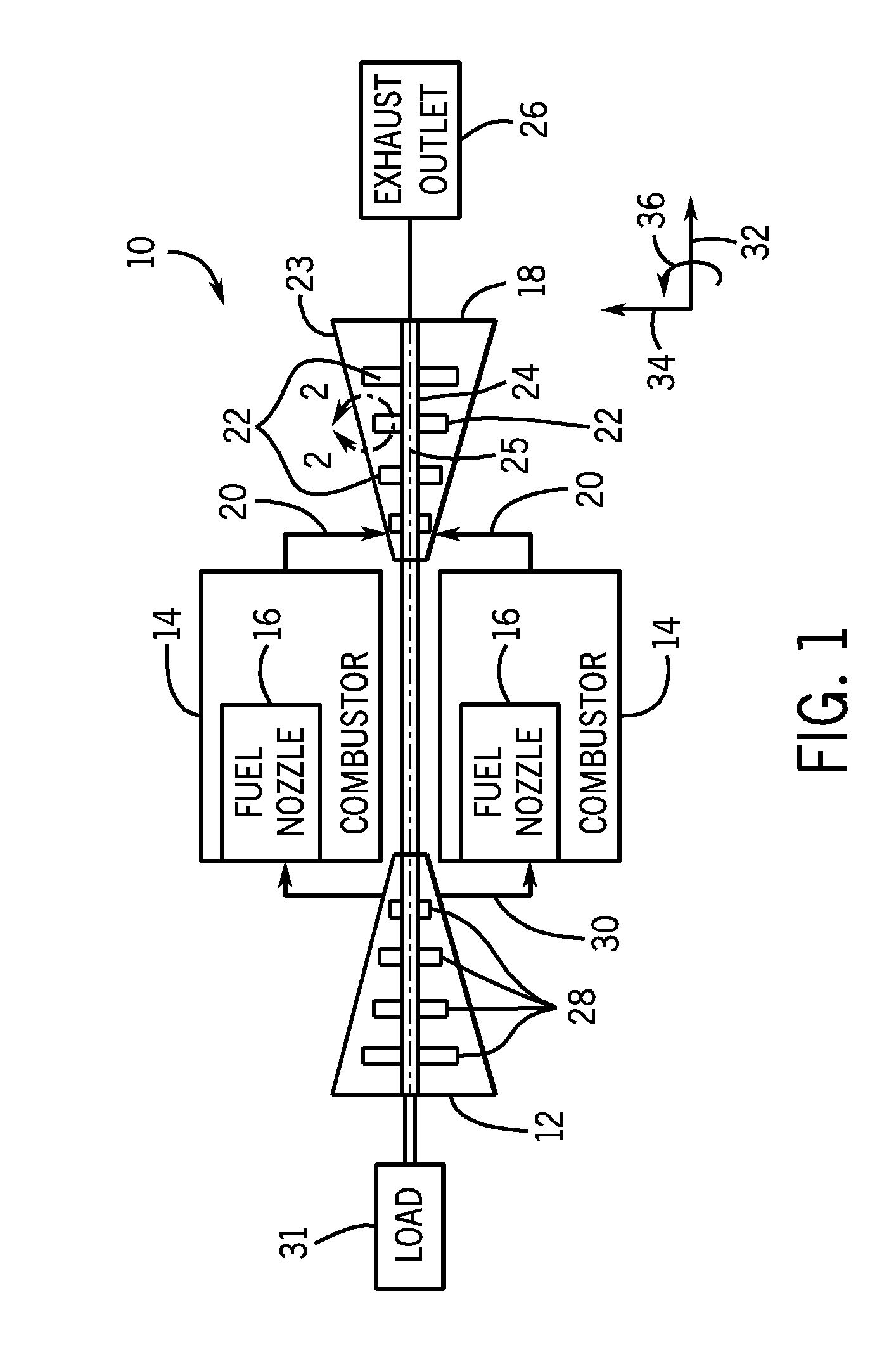
BACKGROUND OF THE INVENTION[0001]The subject matter disclosed herein relates to turbomachines, and, more particularly, a turbomachine blade tip shroud and a casing in a generally parallel configuration.[0002]Turbomachines include compressors and turbines, such as gas turbines, steam turbines, and hydro turbines. Generally, turbomachines include a rotor, which may be a shaft or drum, to which turbomachine blades are attached. Certain turbomachine blades may include tip shrouds and / or seals to meet structural and / or performance requirements. For example, the tip shrouds and / or seals may reduce flow leakage through the cavity or passage between the turbomachine blades and a stationary structural component, such as a static shroud, surrounding the turbomachine blades and the rotor. Existing tip shroud and seal design may not adequately limit or reduce flow leakage between the turbomachine blades and the stationary structural component surrounding the turbomachine blades and the rotor, w...

Claims


Application Information

Patent Timeline
IPC IPC(8): F04D29/38
CPCF01D5/225F01D11/08F05D2250/312
Inventor CHOUHAN, ROHITPIERRE, SYLVAINSIDEN, GUNNAR LEIFVIJAYAN, SANTHOSH KUMARCOTRONEO, JOSEPH ANTHONY
Owner GENERAL ELECTRIC CO
Why Eureka
Eureka Blog
Learn More