Slide Fastener and Slider for Slide Fastener

a slide fastener and slider technology, applied in the direction of slide fasteners, snap fasteners, press-button fasteners, etc., can solve the problems of insufficient contact between the locking pawl and the element, increased costs, and ineffective work of the stopper mechanism, so as to achieve the effect of effective stopper function and not easily detached

a slide fastener and slider technology, applied in the direction of slide fasteners, snap fasteners, press-button fasteners, etc., can solve the problems of insufficient contact between the locking pawl and the element, increased costs, and ineffective work of the stopper mechanism, so as to achieve the effect of effective stopper function and not easily detached

US20130276270A1Active Publication Date: 2013-10-24YKK CORP

Image

  • Slide Fastener and Slider for Slide Fastener
  • Slide Fastener and Slider for Slide Fastener
  • Slide Fastener and Slider for Slide Fastener

Examples


first embodiment

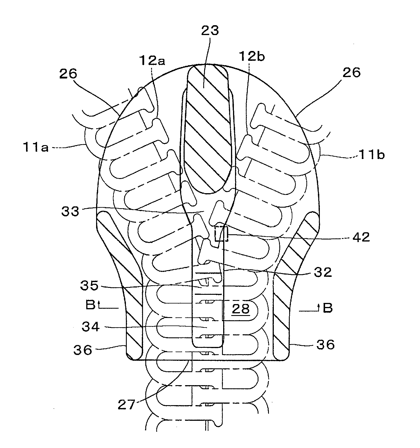
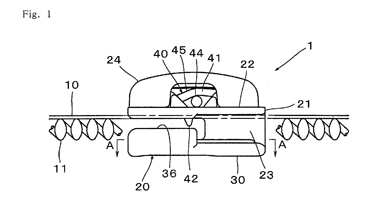
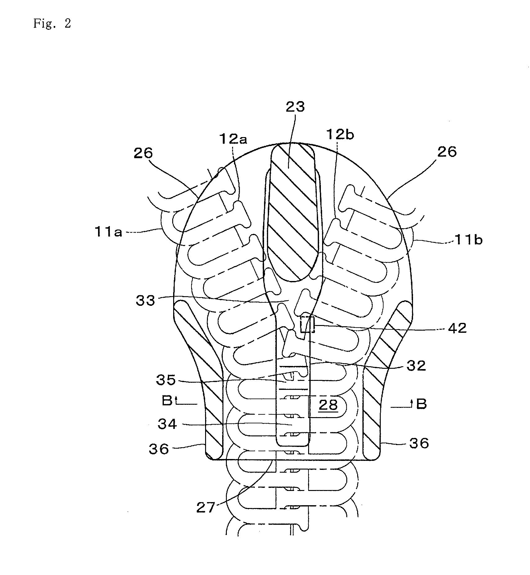
[0031]Hereinafter, preferable embodiments of the invention will be described with reference to the drawings. FIG. 1 is a partial side explanation view that schematically shows a slide fastener 1 in accordance with an embodiment of the invention. FIG. 2 is a partial cross-sectional plan explanation view of a lower wing plate 30 as described later, when viewed from the A-A line in FIG. 1, in which left and right coil-shaped fastener elements 11 (11a, 11b) are represented by dashed lines. FIG. 3 is a longitudinal cross-sectional explanation view of the slide fastener 1 when viewed from the B-B line in FIG. 2. The slide fastener 1 includes: a pair of left and right (hereinafter, left-right and upper-lower (or up-down) directions are based on and with respect to the paper face of FIG. 3) fastener tapes 10 (10a, 10b); a pair of left and right coil-shaped fastener elements (hereinafter also referred to merely as “elements”) 11 (11a, 11b) were sewn at the side ends (open / close edges) opposi...

second embodiment

[0038]Next, a slider 50 in accordance with the invention will be described below. FIG. 10 is a side view of the slider 50.

[0039]FIG. 11 is a cross-sectional explanation view of the slider 50 in a state before a pull 80 is connected thereto. The slider 50 is configured to be substantially similar to the slide fastener slider as disclosed in JP,2008-228808,A, except for a raised portion 62 formed on the upper surface 61 of a lower wing plate 60 as described later. The slider 50 can construct the slide fastener for the rear use by being applied to the fastener tapes 10 where the elements 11 are attached on the rear surface, in place of the slider 10 including the above-described stopper mechanism 40. The slider 50 comprises: a slider body 51, which includes an upper wing plate 52, the lower wing plate 60, and a guide post 53 for linking these upper and lower wing plates 52 and 60; and a stopper mechanism 70, which is mounted on the upper wing plate 52 of the slider body 51 and can prev...


PUM


Abstract

A slider for a slide fastener includes a stopper mechanism formed for “forward use,” in which the surface where coiled fastener elements are attached on a fastener tape is the front surface, can be used for “reverse use,” in which the surface where the coiled fastener elements are attached on the fastener tape is the back surface. The inner surface of the lower blade of the slider body of a slider has a protrusion that extends in the forward-reverse direction from a guiding bar towards a posterior opening. The protrusion has a first horizontal upper surface on the guide bar end of the protrusion that is highest and a second upper surface on the posterior opening end that is lower than the first upper surface.

Description

BACKGROUND OF THE INVENTION[0001]The present invention relates to a slide fastener and a slider for a slide fastener, and more particularly relates to a slide fastener in which a slider having a stopper function is adopted in a fastener tape of a so-called “rear use” where the surface on which a coil-shaped fastener element is attached is used as a rear surface of the fastener tape, and a slider for such a slide fastener.BACKGROUND OF THE INVENTION[0002]A slide fastener as one type is known in which a stopper mechanism is incorporated into a slider that can open and close between left and right fastener tapes by a user moving the slider via a pull. One example of such a slider is disclosed in e.g. JP,S63-145605,A. The stopper mechanism includes: a cam shaft for rotatably link the pull to an upper wing plate of the slider; a plate spring, which is located at an initial position when a user does not take the pull and displaced from the initial position by the action of the cam shaft w...

Claims


Application Information

Patent Timeline
24 Oct 2013
Publication
US20130276270A1
IPC
A44B19/26; A44B19/40
CPC
A44B19/26; A44B19/403; A44B19/308; Y10T24/2561; Y10T24/2582; A44B19/12; A44B19/30
Inventors
HAMADA, YOSHIKAZU; KEYAKI, KEIICHI