Valve for switching waterways and adjusting flow

Active Publication Date: 2013-10-24
XIAMEN SOLEX HIGH TECH IND CO LTD
14 Cites 0 Cited by

AI-Extracted Technical Summary

Problems solved by technology

Because of the separate set of the waterway switch valve and the flow adjusting valve, the defects are present: 1 the space occupation is large because of the increased bathroom acc...

Benefits of technology

[0024]3 the projection of the switch part is fan-shaped with easy flow adjustment;
[0025]4 the handle swings relatively, and then the deflector rod is driven to swing relative to the limiting body, and the control piece is moved to slide relative to the fixed seat through the lower end of the deflector rod, and then the control face slides relative to the fixed face, and then the flow adjustment is achieved, the handle rotates relatively, and then the limiting body and the control piece are driven to rotate relative to the fixed seat, and the control piece rotates relative to the fixed face, and then the waterways switch is achieved, therefore the waterways switch and the flow adjustment can be controlled only through a handle with convenient and fast operation, and the two fu...

Abstract

A valve for switching waterways and adjusting flow has a fixed seat, a control piece and an operation mechanism. The fixed seat is provided with a fixed face, an inlet waterway and two outlet waterways, the inlet port of the inlet waterway and the outlet ports of the outlet waterway are arranged on the fixed face. The control piece is provided with a control face that is relied on the fixed face hermetically and a communicating groove that is concavely arranged on the control face. The operation mechanism is connected with the fixed seat and the control piece, and can drive the control piece to move, and then the control face can be driven to rotate and slide relative to the fixed face.

Application Domain

Operating means/releasing devices for valvesMultiple way valves +2

Technology Topic

EngineeringStreamflow +1

Image

  • Valve for switching waterways and adjusting flow
  • Valve for switching waterways and adjusting flow
  • Valve for switching waterways and adjusting flow

Examples

  • Experimental program(1)

Example

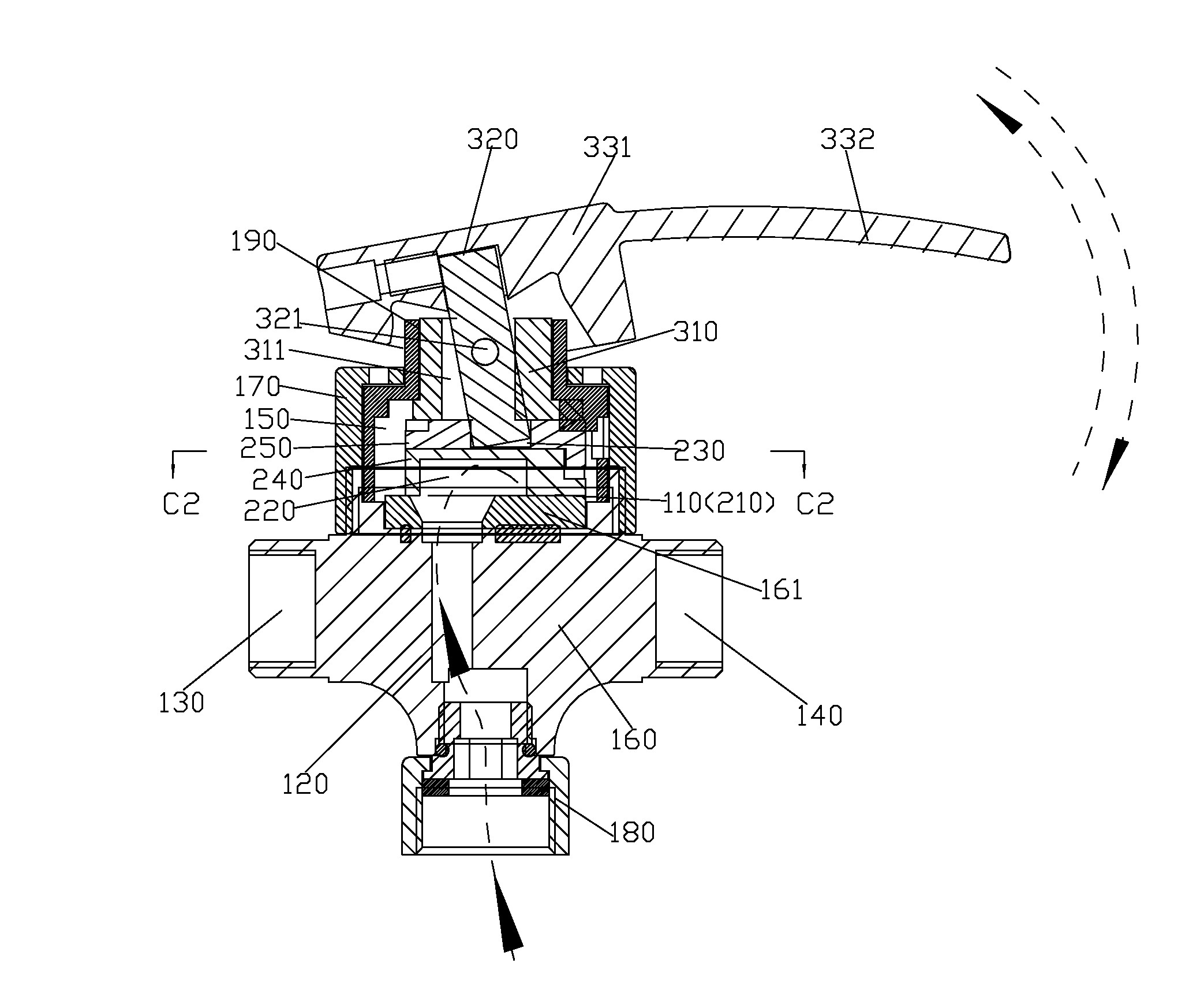
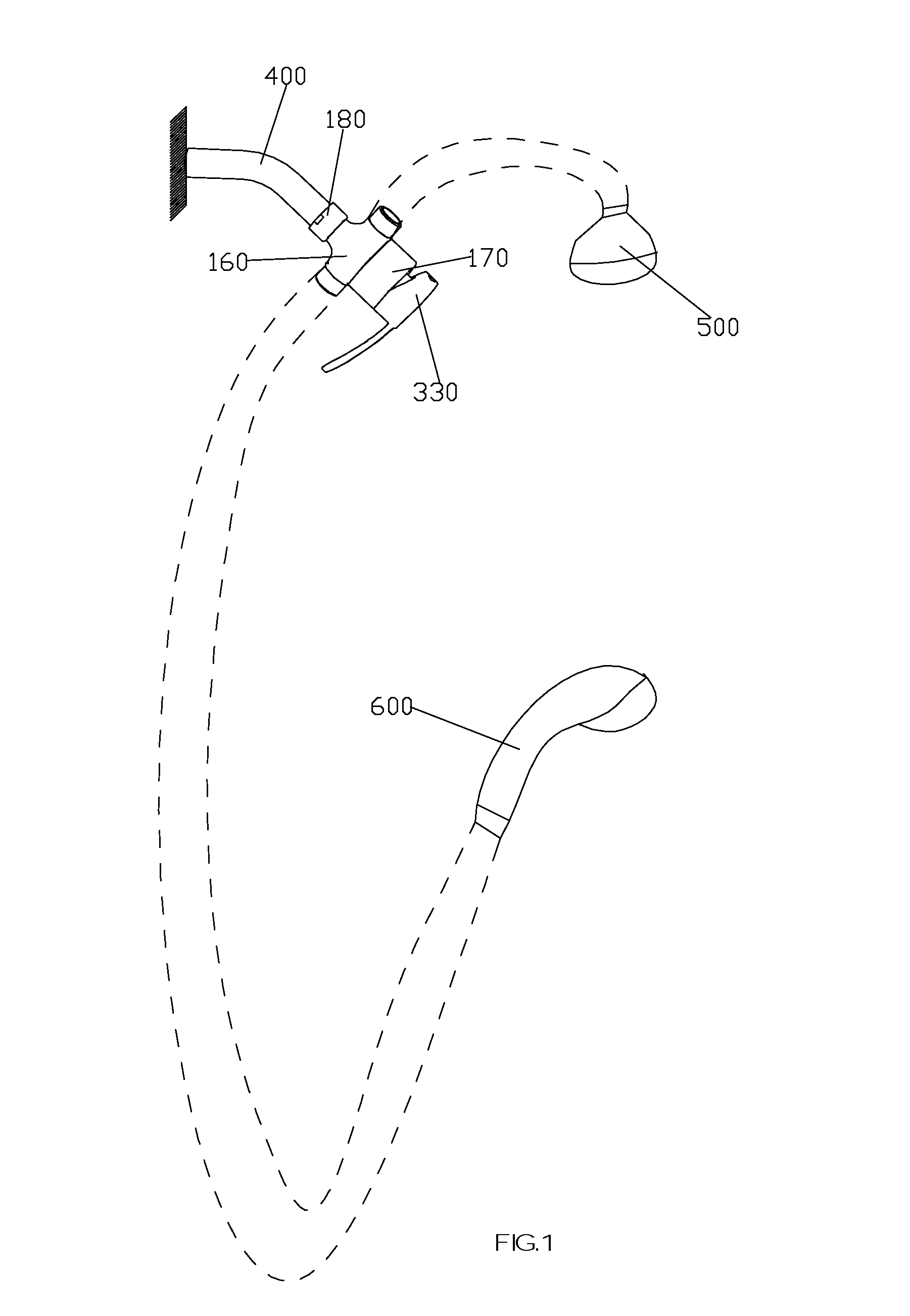
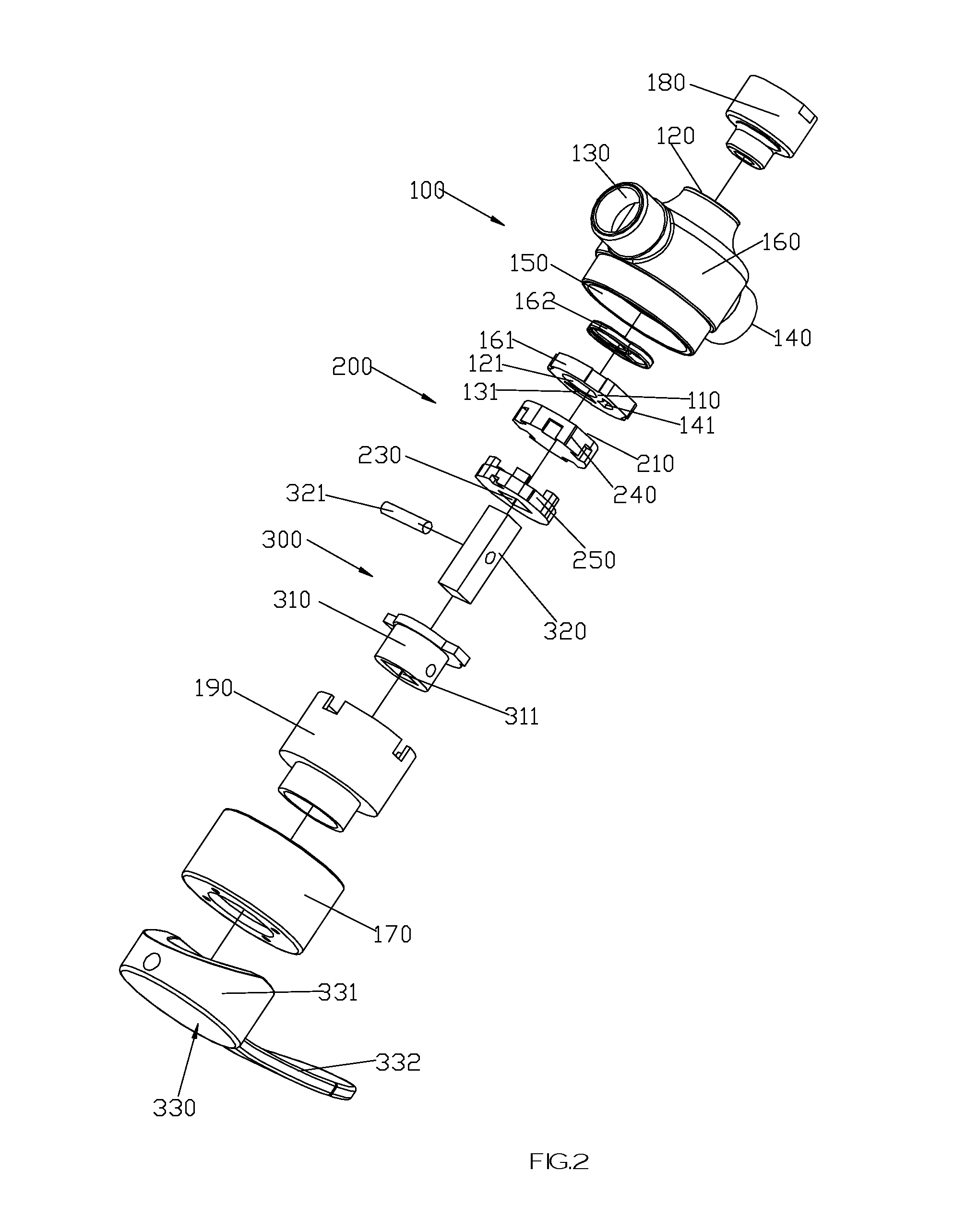
[0044]According to FIG. 1 to FIG. 14, the valve for switching waterways and adjusting flow, comprises a fixed seat 100, a control piece 200 and an operation mechanism 300.
[0045]The fixed seat 300 comprises a body 160, a gland nut 170, a connector 180 and a fixed shell 190.
[0046]The top surface of the body 160 is concavely arranged to be a groove, and a stator 161 is fixed on the bottom surface of the groove, and the top surface of the stator 161 is defined as a fixed face 110, and a first inlet hole and two first outlet holes arranged in the stator 161 in an against and penetrating manner. And it is better that a gasket 162 is arranged between the stator 161 and the bottom surface of the groove. A second inlet hole and two second outlet holes are arranged in the body 160. And the stator 161 is mounted in the groove of the body 160, so that: the first inlet hole is communicated with the second inlet hole to generate the inlet waterway 120, and the inlet port 121 of the inlet waterway 120 is arranged on the fixed face 110;
[0047]The two first outlet holes are communicated with the two second outlet holes respectively to generate two outlet waterways 130 and 140, and the outlet ports 131 and 141 of the two outlet waterways 130 and 140 are arranged on the fixed face 110, wherein, the inlet port 121 and the outlet ports 131 and 141 are arranged alternately, and the outlet ports 131 and 141 is arranged symmetrically relative to the inlet port 121.
[0048]The connector 180 is fixed to the body 160, wherein, the connector 180 can be fixed to and communicated with the impending arm 400, and water can be introduced into the inlet waterway 110 through the connector 180 from water source.
[0049]The fixed shell 190 is connected to the groove of the body in a locating manner, and the gland nut 170 is sleeved to the fixed shell 190 and screwed with the groove of the body 160, so that the fixed shell 190, the gland nut 170 and the body 160 are fixed together, wherein, the groove and the inner hole of the fixed shell 190 of the gland nut are cooperating with each other to form a mounting cavity 150.
[0050]The control piece 200 comprises a rotor 240 and a holding body 250. The bottom surface of the rotor 240 is defined as a control face 210, a communicating groove 220 is concavely arranged on the bottom of the rotor 240, and a connecting groove 230 is concavely arranged on the top surface of the holding body 250. The bottom surface of the holding body 250 is relied on the top surface of the rotor 240 and a synchronous and coaxial rotation connection relationship is generated. And the communicating groove 220 is divided into a communicating part and a switch part, and the projection of the switch part is fan-shaped.
[0051]The rotor 240 is mounted in the mounting cavity 150 in a moving manner, and under the relying action of the gland nut 170 and the limiting body 310, the control face 210 of the rotor 240 is relied on the fixed face 110 of the stator 161 hermetically, wherein, the communicating part of the communicating groove 220 is always communicated with the inlet port 121, and the switch part can be communicated with the two outlet ports 131 and 141 alternatively and can be between the two outlet ports 131 and 141 (the interval part between the two outlet ports 131 and 141 is bigger than the switch part), and according to FIG. 9 to 14, three switch states are described respectively.
[0052]The communicating groove 220, the inlet port 121 and the outlet ports 131 and 141 are cooperating with each other, so that: the relative rotation between the control face 210 and the fixed face 110 can achieved the switch between the outlet ports 131 and 141 at least, and the relative sliding between the control face 210 and the fixed face 110 can achieve flow adjustment.
[0053]The operation mechanism 300 comprises a limiting body 310, a deflector rod 320 and a handle 330.
[0054]The limiting body 310 is sleeved in the mounting cavity 150 of the fixed seat 100 in a rotating manner, and is provided with a penetrating hole 311 inside of which the section is rectangle.
[0055]The section of the deflector rod 320 is rectangle, the lower end of which is inserted into the connecting groove 230 of the control piece 200, and of which the first direction space is adaptive to the corresponding direction space of the connecting groove 230, and of which the second direction space is smaller than the corresponding direction space of the connecting groove 230, and the first and the second directions are vertical to each other. The first direction space of the deflector rod 320 is adaptive to the first direction space of the penetrating hole 311, and the second direction space of the deflector rod 320 is smaller than the corresponding direction space of the penetrating hole 311. The upper end of the deflector rod 320 passes through the penetrating hole 311, and a pivot 321 at the other end is arranged to passes through the middle of the deflector rod 320 and the limiting body 310.
[0056]The handle 330 comprises a fixing part 331 and a hand shank 332 that are fixed together, a fixing groove is arranged under the fixing part 331, which is connected with the upper end of the deflector rod 320 in a fixing manner.
[0057]According to FIG. 1, one outlet waterway 130 is communicated with the head shower 500, another outlet waterway 140 is communicated with the handheld shower 600.
[0058]According to FIGS. 9 and 10, at this time, the switch part of the communicating groove 220 of the rotor 240 is between the outlet ports 131 and 141, and the water stop state is present, and no water comes out of the two outlet waterways 130 and 140.
[0059]According to FIGS. 11 and 12, the handle 330 can swing up and down relative to the fixed seat 110, and the deflector rod 320 can be driven to swing around the pivot 321 relative to the limiting body 310, the holding body 250 is moved by the lower end of the deflector rod 320 to slide relative to the stator 161, and then the rotor 240 slides relative to the stator 161, and then the control face 210 slides relative to the fixed face 110, so that the intersecting area of the switch part and the outlet ports is changed for flow adjustment.
[0060]According to FIGS. 13 and 14, the handle 330 is rotated relative to the fixed seat 100, and then the limiting body 310, the holding body 250 and the rotor 240 are driven to rotate relative to the stator 161, and then the control face 210 is rotated relative to the fixed face 110, so that the switch part is selectively at the outlet port 131, 141 or the position between the two outlet ports 131 and 141, such as: the switch part is at the outlet ports 131, and then the outlet ports 131 is communicated with the switch part, and then the outlet waterway 130 is communicated with the inlet waterway 120, and then water flows out of the outlet waterway 130; or the switch part is at the outlet ports 141, and then the outlet ports 141 is communicated with the switch part, and then the outlet waterway 140 is communicated with the inlet waterway 120, and then water flows out of the outlet waterway 140; or the switch part is between the two outlet ports 131 and 141 and at water stop state, so that the waterway switch function is achieved.
[0061]The invention has been described with reference to the preferred embodiments mentioned above; therefore it cannot limit the reference implementation of the invention. It is obvious to a person skilled in the art that structural modification and changes can be carried out without leaving the scope of the claims hereinafter and the description above.
INDUSTRIAL APPLICABILITY
[0062]In the valve for switching waterways and adjusting flow in the present invention, the control piece is driven to move by the operation mechanism, and then the control face is driven to rotate and slide relative to the fixed face, the relative rotating can achieve the switch function of a plurality of outlet ports and the waterways switch function, and the relative sliding can achieve the flow adjusting function.

PUM

no PUM

Description & Claims & Application Information

We can also present the details of the Description, Claims and Application information to help users get a comprehensive understanding of the technical details of the patent, such as background art, summary of invention, brief description of drawings, description of embodiments, and other original content. On the other hand, users can also determine the specific scope of protection of the technology through the list of claims; as well as understand the changes in the life cycle of the technology with the presentation of the patent timeline. Login to view more.

Similar technology patents

Pullbox assembly

InactiveUS6881899B1easily assembleeasily attach and remove
Owner:TRANGSRUD JULIAN P

Electric Actuator

InactiveUS20080129133A1easily assemble
Owner:DANAHER MOTION STOCKHOLM AB

Hydraulic relief valve

InactiveUS20070056632A1easily assemblemake up function be improve
Owner:VOLVO CONSTR EQUIP

Composite optical film

InactiveUS20100086743A1light efficiency be enhanceeasily assemble
Owner:ETERNAL MATERIALS CO LTD

Connector for electrical wire-carrying conduits

InactiveUS7793988B1easily assemble
Owner:ATKORE STEEL COMPONENTS INC

Classification and recommendation of technical efficacy words

  • easy flow adjustment
Why Eureka
Try Eureka