Control method of spraying robot

The technology of a spraying robot and control method, which is applied in the direction of spraying devices, etc., can solve the problems of inconvenient flow adjustment of nozzles, etc.

Inactive Publication Date: 2019-08-27
CHONGQING NEWSTAR TECH CO LTD
View PDF5 Cites 0 Cited by
  • Summary
  • Abstract
  • Description
  • Claims
  • Application Information

AI Technical Summary

Problems solved by technology

[0004] The present invention intends to provide a control method of a spraying robot to solve the problem of inconvenient flow adjustment of nozzles of existing spraying robots

Method used


Image

  • Control method of spraying robot
  • Control method of spraying robot
  • Control method of spraying robot

Examples


Embodiment Construction

[0032] The present invention will be described in further detail below by means of specific embodiments:

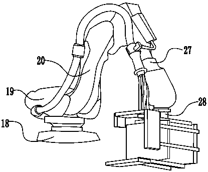
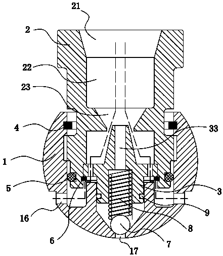
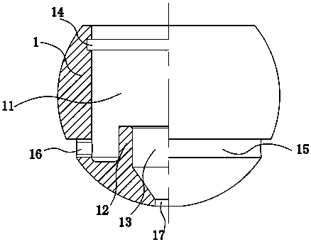
[0033] The reference signs in the drawings of the description include: ball head seat 1, first groove 11, first protrusion 12, first through hole 13, first card groove 14, lower sealing groove 15, air inlet 16, feed Port 17, nozzle body 2, discharge port 21, diffusion chamber 22, vacuum chamber 23, disc installation hole 24, second groove 25, second card slot 26, nozzle 3, disc 31, air passage 32, the second One paint channel 33, the second paint channel 34, the third card slot 35, the nozzle body snap ring 4, the nozzle body seal ring 5, the nozzle snap ring 6, the one-way valve ball 7, the compression spring 8, the nozzle seal ring 9, the base 18. The first mechanical arm 19, the second mechanical arm 20, the third mechanical arm 27, the connecting arm 28, the connecting plate 29, the connecting bar 30, the pipeline connecting plate 36, the upper spraying plate 37, the ...


PUM


Abstract

The invention discloses a control method of a spray coating robot. According to the method, spray coating flow rate calculation is performed before fixed mold spray coating and movable mold spray coating, so that the spray coating flow rate can be regulated for meeting the mold temperature requirements. The method has the advantages that the automatic and manual switching operation can be performed, and the design is reasonable.

Description

technical field [0001] The invention relates to a spraying robot, and specifically discloses a control method for a spraying robot. Background technique [0002] Spraying robot, also called painting robot, is an industrial robot that can automatically spray paint or spray other coatings. The spraying robot mainly includes a manipulator and a controller. The manipulator is provided with a power source for driving the manipulator, such as an oil pump, an oil tank, and a motor. The free end of the manipulator is generally connected with a spray frame and a nozzle for spraying operation. [0003] However, the existing spraying robot still has the following defects: 1. The nozzle and the paint valve are designed in one piece, and the volume is too large, so the nozzle can only spray on an inclined plane, and the spraying surface of the nozzle in the mold cavity will produce a spraying blind area. Due to the limitation of the mold structure, it cannot be better. In order to form...

Claims


Application Information

Patent Timeline
Patent Type & Authority Patents(China)
IPC IPC(8): B05B13/04B05B12/00
Inventor 傅建设张朝全袁红
Owner CHONGQING NEWSTAR TECH CO LTD
Why Eureka
Try Eureka