
Novel blast furnace stokehole molten iron silicon increasing device

A technology of molten iron and blast furnace, which is applied in the field of silicon-increasing devices for molten iron in front of a new type of blast furnace, which can solve the problems of scattered materials, inability to move, and cumbersome feeding operations in the feeding bin.

Pending Publication Date: 2021-06-08
临沂玫德庚辰金属材料有限公司
View PDF0 Cites 0 Cited by
  • Summary
  • Abstract
  • Description
  • Claims
  • Application Information

AI Technical Summary

Problems solved by technology

[0003] In the current existing technology, most of the silicon-increasing devices in front of the blast furnace use fixed conduits for feeding, which cannot achieve the effect of precise positioning, and cannot be moved, which cannot meet the needs of various operating conditions. The traditional silicon-increasing device in front of the blast furnace The operation of feeding the material to the silo is cumbersome, especially the material in bags, which may easily cause the material to scatter

Method used

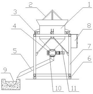
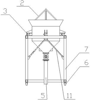
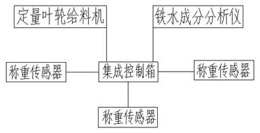

Image

  • Novel blast furnace stokehole molten iron silicon increasing device
  • Novel blast furnace stokehole molten iron silicon increasing device
  • Novel blast furnace stokehole molten iron silicon increasing device

Examples


Embodiment 1

[0032] Using the present invention to increase the iron water in front of the blast furnace, the amount of iron water is 81.6T, and the iron water component analyzer is analyzed. The amount of silicon containing 1.02% in the iron water is 1.75% silicon, 75% silicon iron. The component is Si65.6%, density 3.98t / m 3 , Volume density is 2.5T / m 3 , Granularity <50mm, the target silicon is 1.57%, the target silicon iron is 1.0t, and the bag is used through the car through the triangular cutter 2 to open the bunker 1, ready for the raw material The position of the present invention is adjusted by the travel wheel 6, and the position adjustment is adjusted, the outlet position of the conductive slip 5 is manually adjusted, and the outlet position is positive to the target, that is, the front iron groove 9, the integrated control box 8 The controller is provided, the controller calculates the added silicon iron according to the data of the iron water component analyzer, and the set of...

Embodiment 2

[0034] Based on the above embodiment, the data foundation is changed, and the mounting of the triangulation cutter 2 is performed, and the test data retains two digits after the test data, the test data retains two digits after the test data. Conclusion data As shown in the following table:

[0035] Numbering Iron water Silicon target delivery Target Si content Real silicon Real Si content Total cost of charge after using a triangular cutter 2 Did not use a triangular cutter 2 1 86.00T 0.90T 1.31% 0.90T 1.31% 2.00min 8.00min 2 76.20T 0.90T 1.45% 0.90T 1.45% 2.00min 8.00min 3 82.10T 1.20T 1.45% 1.20T 1.45% 3.00min 10.00min

[0036] It can be seen that the three weighing sensor 3 employed by the present invention simultaneously, the monitoring weight is higher, the accuracy is higher, and the accuracy of the Si amount and the amount of silicon is maintained, so that it remains at very small. Inside the error.

[0037]At the same t...


PUM

PropertyMeasurementUnit
Granularityaaaaaaaaaa

Abstract

The invention discloses an novel blast furnace stokehole molten iron silicon increasing device which comprises a rack, walking wheels are connected to bottom feet of the rack, the upper end of the rack is connected with a weighing sensor, the weighing sensor is connected with a stock bin, the upper end of the stock bin is open and connected with a triangular frame type cutting knife, and the bottom of the stock bin is connected with a quantitative impeller feeding machine. The quantitative impeller feeding machine is connected with a rotary connecting piece, the rotary connecting piece is connected with a material guiding articulated chute, a cross beam on the upper portion of the rack and a stand column are connected and fixed through a cable-stayed supporting arm, and the side face of the rack is connected with an integrated control box. The novel blast furnace stokehole molten iron silicon increasing device can be moved at will, precisely increase silicon at a fixed point, precisely calculate the silicon increasing amount, reduce the error, and facilitates feeding, the material flow is adjustable, and the labor consumption is reduced.

Description

Technical field [0001] The present invention relates to the technical field of sustained silicon apparatus, and in particular, a new type of blast furnace furnace furnace furnace furnace furnace resilings. Background technique [0002] When the blast furnace smelting casting iron water, when the iron water contains a target value of the iron water than the required grade, the silicon content can be adjusted to the target value through iron water silicon technology, and sometimes in order to obtain high quality, pure iron species, low Silica and blast furnace front iron pretreatment technology, add iron water to the target value of the required grade. [0003] At present, in the prior art, most of the silicon before the blast furnace uses a fixed catheter to be added, and the effect of accurate positioning cannot be achieved, and it is unable to move. The need for multiple operations, the traditional blast furnace furnace The material is increasingly increasing, especially the mat...

Claims


Application Information

Patent Timeline
IPC IPC(8): B65G65/48B65G65/32B65G69/00B65B69/00C21C1/00
CPCB65B69/0008B65B69/0033B65G65/32B65G65/48B65G69/00C21C1/00
Inventor 郭玉国崔士选陈梦霞孙永福汤化鹏王洪刚
Owner 临沂玫德庚辰金属材料有限公司
Learn More