Complex harness

a technology of complex harnesses and wire harnesses, applied in the direction of insulated conductors, power cables, cables, etc., can solve the problems of complicated wiring work of these cables, and achieve the effect of efficient use of wiring spa

Active Publication Date: 2013-10-24
HITACHI METALS LTD
View PDF8 Cites 75 Cited by
  • Summary
  • Abstract
  • Description
  • Claims
  • Application Information

AI Technical Summary

Benefits of technology

[0022]According to one embodiment of the invention, a complex harness can be provided that all

Problems solved by technology

Thus, the installation thereof is desired to be improved since the wiring space of

Method used


Image

  • Complex harness
  • Complex harness
  • Complex harness

Examples


Embodiment Construction

[0028]The embodiment of the invention will be described below in conjunction with the appended drawings.

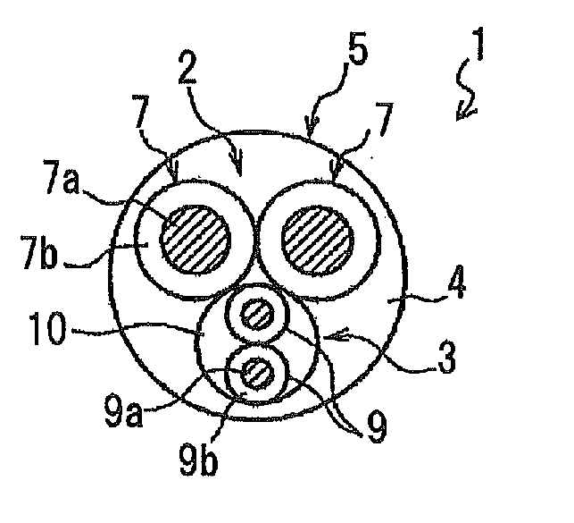
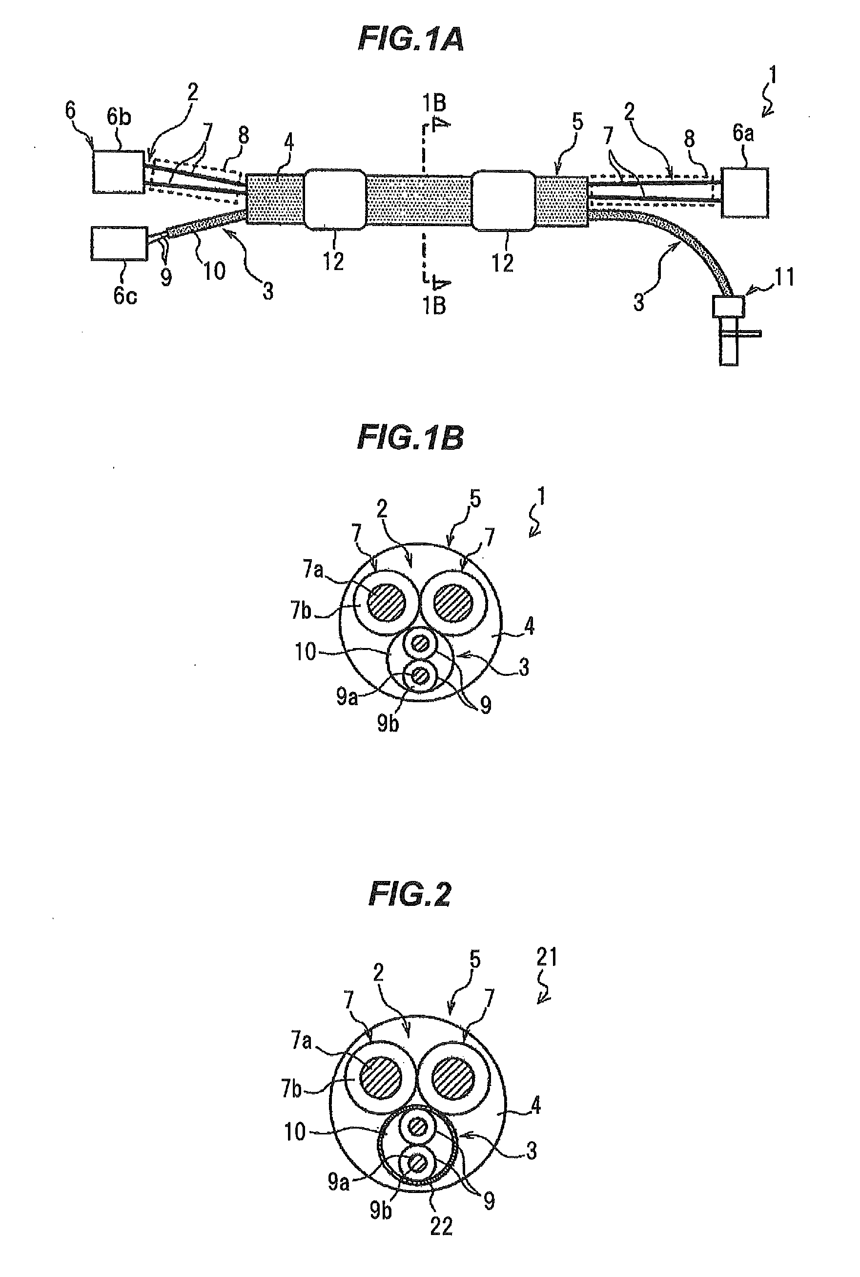
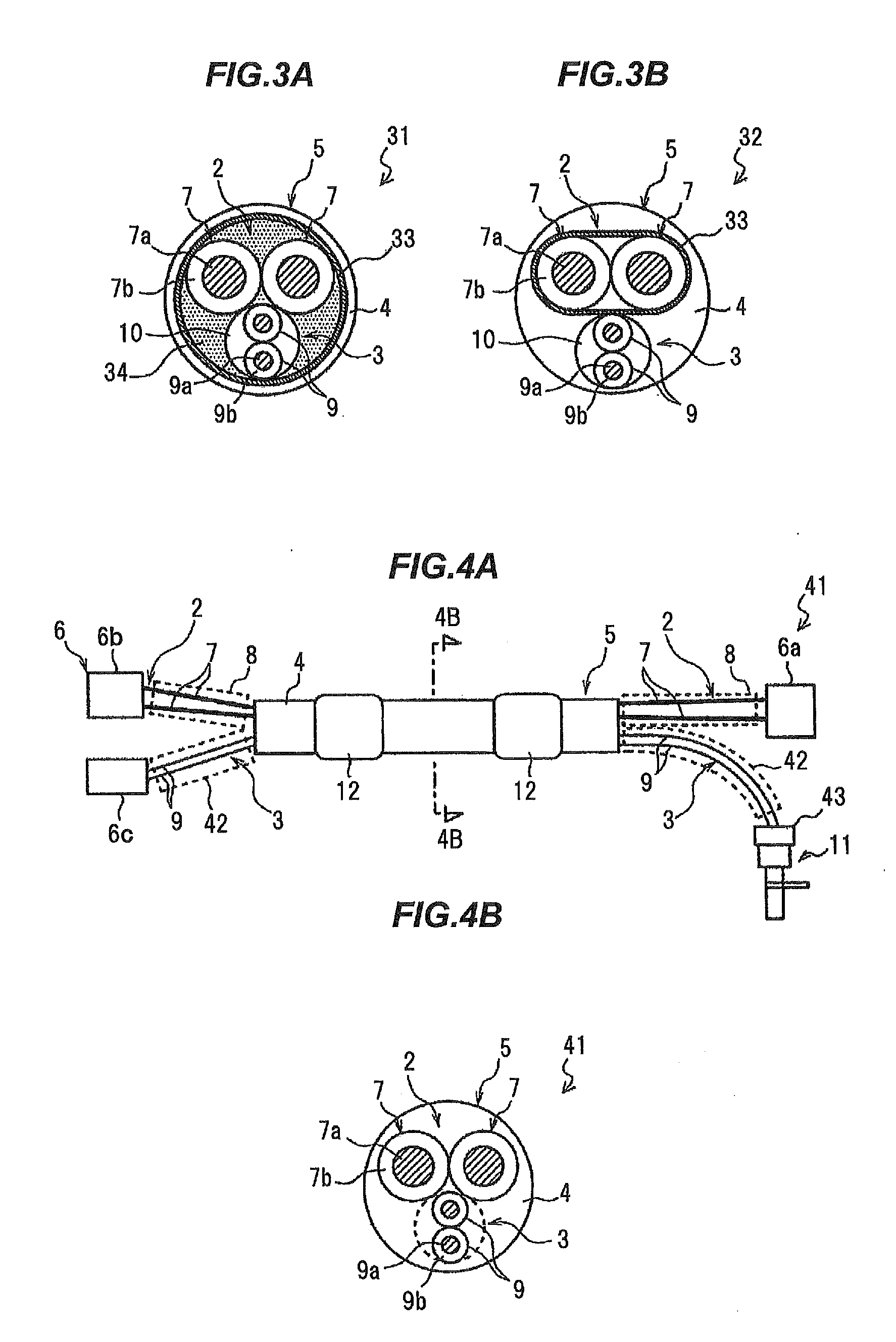
[0029]FIGS. 1A and 1B are diagrams illustrating a complex harness in the present embodiment, wherein FIG. 1A is a plan view and FIG. 1B is a cross sectional view taken on line 1B-1B.

[0030]As shown in FIGS. 1A and 1B, a complex harness 1 is provided with a composite cable 5 composed of an electric brake cable 2 and an ABS sensor cable 3 which are integrated by covering with a common outer sheath 4. In addition, the complex harness 1 is configured such that the electric brake cable 2 and the ABS sensor cable 3 are separated at end portions of the composite cable 5 and a connector 6 is provided at an end portion of least at one of the cables 2 and 3.

[0031]The electric brake cable 2 is composed of two power wires 7 and is mainly used as a conducting path for passing an electric current which is caused to flow therethrough by pressing a given button after stopping a vehicle to operate ...


PUM

PropertyMeasurementUnit
Adhesion strengthaaaaaaaaaa
Currentaaaaaaaaaa
Thermoplasticityaaaaaaaaaa

Abstract

A complex harness includes a composite cable including an electric brake cable, an ABS sensor cable and an outer sheath. The electric brake cable and the ABS sensor cable are integrated by being commonly covered with the outer sheath.

Description

[0001]The present application is based on Japanese patent application Nos. 2012-096729 and 2012-215636 filed on Apr. 20, 2012 and Sep. 28, 2012, respectively, the entire contents of which are incorporated herein by reference.BACKGROUND OF THE INVENTION[0002]1. Field of the Invention[0003]The invention relates to a complex harness for a vehicle.[0004]2. Description of the Related Art[0005]An ABS sensor used in an ABS (Anti-lock Brake System) of a vehicle is conventionally known. The ABS sensor is to measure a rotation speed of a wheel and a sensor portion (sensor head) of the ABS sensor is provided in the vicinity of the wheel. The sensor portion provided in the vicinity of the wheel is connected to a control device (electronic control unit) provided on a vehicle body via an ABS sensor cable.[0006]In recent years, an electric brake in which braking is controlled by electricity in place of hydraulic pressure is becoming popular. An electric parking brake (EPB) which is a motorized par...

Claims


Application Information

Patent Timeline
IPC IPC(8): H01B7/00
CPCH01B7/0045B60R16/0215H01B3/30H01B3/50H01B3/54H01B9/003
Inventor HAYAKAWA, YOSHIKAZUESHIMA, HIROTAKA
Owner HITACHI METALS LTD
Why Eureka
Try Eureka