Vibration generator

a technology of vibration generator and generator body, which is applied in the direction of dynamo-electric machines, electrical apparatus, etc., can solve the problems of reducing the size of the vibration generator, difficult to assemble the structure, and inability of the vibration generator to sufficiently generate vibration, etc., to achieve the effect of preventing deflection of the vibrating body and stopping the vibrating body within a short period of tim

Inactive Publication Date: 2013-10-24
SANYO SEIMITSU
View PDF3 Cites 8 Cited by
  • Summary
  • Abstract
  • Description
  • Claims
  • Application Information

AI Technical Summary

Benefits of technology

[0009]The present invention provides a vibration generator capable of cost-effectively preventing deflection of a vibrating body without impeding the reduction of a size of the vibration generator and capable of stopping the vibrating body within a short period of time.
[0011]In the present invention, the vibrating body is supported by the spring only at one thrust-direction side thereof. This makes it possible to increase the stroke of the vibrating body. The vibration generator of the present invention includes the shaft arranged to allow the vibrating body to slide along the shaft in the thrust direction. It is therefore possible to prevent the vibrating body from being deflected in a radial direction. This makes it possible to smoothly vibrate the vibrating body in the thrust direction. Since the shaft prevents radial deflection of the vibrating body, it is possible to prevent the vibrating body from making contact with the coil. This makes it possible to prevent disconnection of the coils and damage of the magnet arranged in the vibrating body. With the structure in which the shaft is arranged and in which the vibrating body is supported by the spring only at one thrust-direction side thereof, it is possible to facilitate the assembling of the vibration generator.
[0013]In the present invention, the bearing slides along the shaft and the vibrating body vibrates in the thrust direction. This makes it possible to smoothly vibrate the vibrating body in the thrust direction.
[0015]In the present invention, it is possible to reduce the friction generated between the shaft and the bearing. This makes it possible to smoothly vibrate the vibrating body. Since a certain degree of friction is generated between the shaft and the bearing, it is possible to stop the vibrating body within a short period of time.
[0017]In the present invention, it is possible to increase the radius and circumferential length of the coil, eventually increasing the volume of the coil. By increasing the radius and circumferential length of the coil, it becomes possible to widen the region existing radially inward of the coil. This makes it possible to increase the radial dimension of the vibrating body. The magnet arranged in the outer peripheral portion of the vibrating body with an increased radial dimension has an increased volume. This makes it possible to lower the performance of the magnet. It is therefore possible to reduce the cogging force generated during the vibration of the vibrating body.
[0018]According to the present invention, the vibrating body is supported by the spring only at one thrust-direction side thereof. This makes it possible to increase the stroke of the vibrating body. Thus, the reduction of the size of the vibration generator is not hindered. Since the vibrating body is supported by the spring only at one thrust-direction side thereof, it becomes possible to assemble the vibration generator with ease. Inasmuch as the shaft prevents deflection of the vibrating body, it is possible to smoothly vibrate the vibrating body. Moreover, it is possible to prevent the vibrating body and the coil from making contact with each other. This makes it possible to prevent disconnection of the coil and damage of the magnet installed in the vibrating body. Since the vibrating body slides along the shaft, it becomes possible to stop the vibration of the vibrating body within a short period of time.

Problems solved by technology

This makes it impossible for the vibration generator to sufficiently generate vibration.
Moreover, the structure in which the springs are installed at the thrust-direction opposite sides of the vibrating body becomes an obstacle in reducing the size of the vibration generator.
It is difficult to assemble the structure in which the springs are installed at the thrust-direction opposite sides of the weight.
However, the method of filling the viscous fluid into the vibration generator cannot prevent leakage of the viscous fluid unless the fluid-tightness of a housing serving as an outer shell of the vibration generator is kept high.
The high-accuracy machining tends to impede cost saving.

Method used


Image

  • Vibration generator
  • Vibration generator
  • Vibration generator

Examples


first embodiment

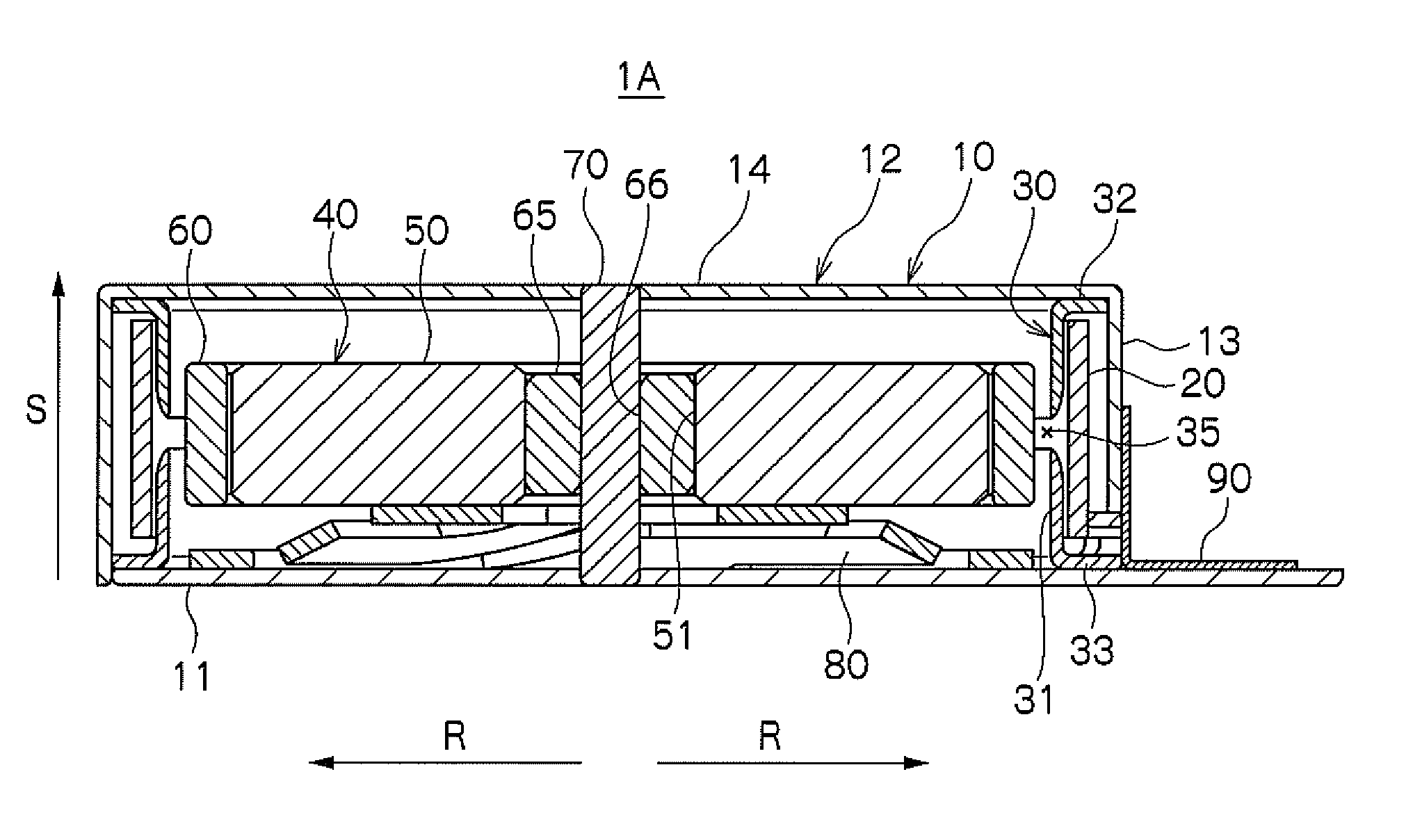
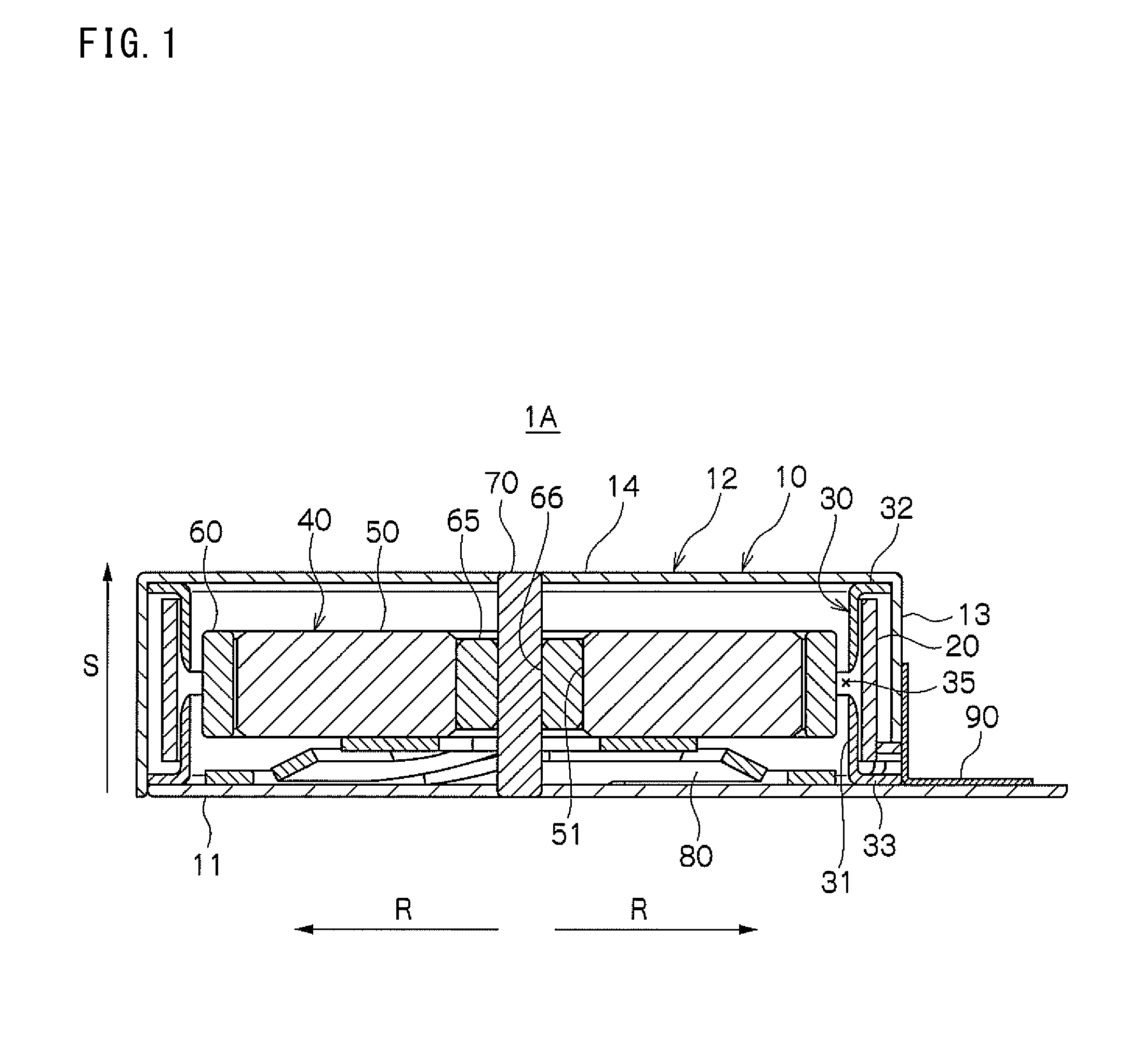
[0035]A vibration generator 1A according to a first preferred embodiment of the present invention will be described in detail with reference to FIGS. 1 and 2. The radius direction of the vibration generator 1A designated by reference symbol R in FIG. 1 is a radial direction. The height direction of the vibration generator 1A designated by reference symbol S in FIG. 1 is a thrust direction.

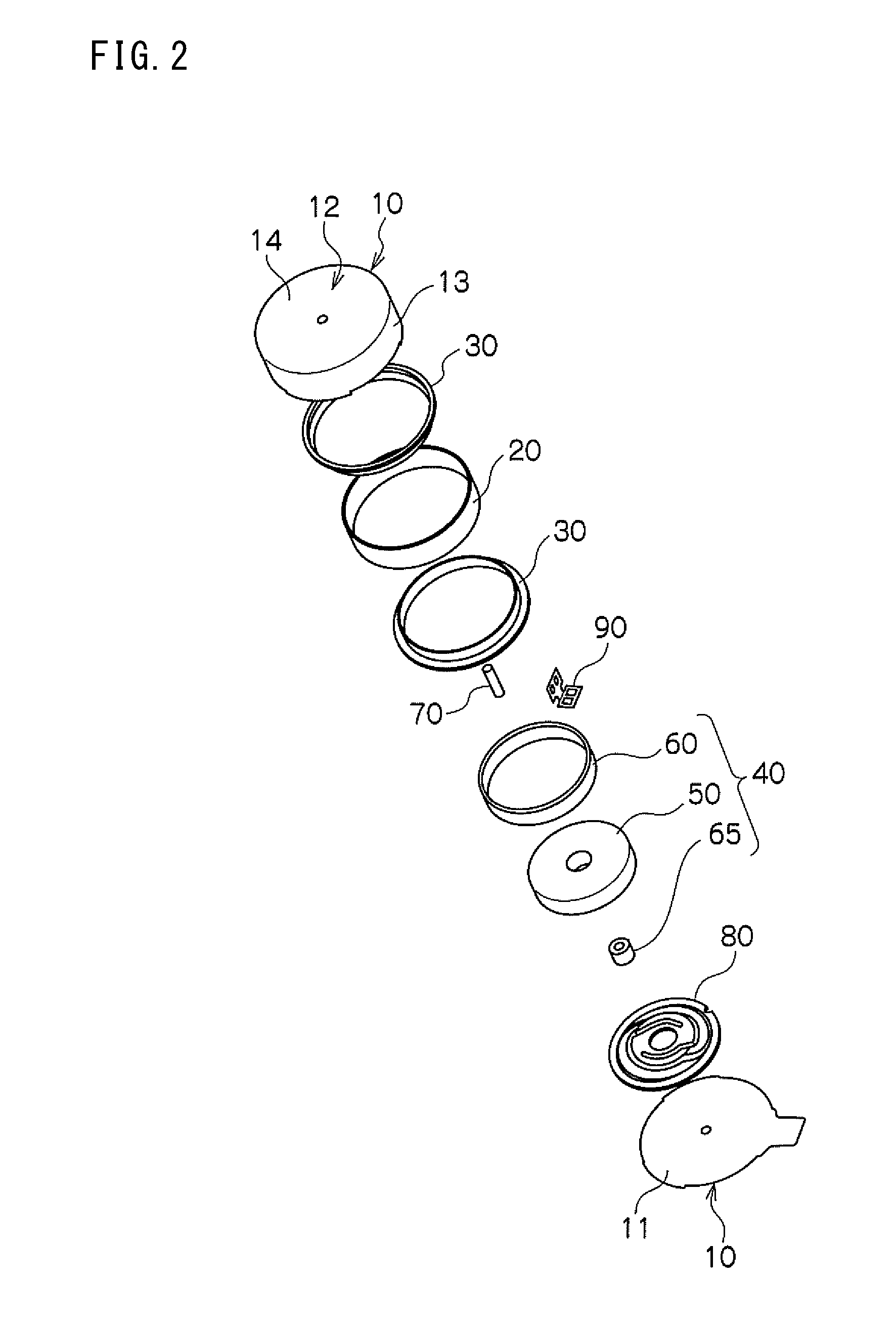
[0036]The vibration generator 1A preferably includes a housing 10 serving as an outer shell. The housing 10 preferably includes an end plate 11 serving as a bottom surface of the vibration generator 1A and a case 12 capped on the end plate 11. The case 12 is one-piece formed by an annular peripheral wall surface 13 surrounding the periphery of the vibration generator 1A and a top surface 14 covering the top portion of the vibration generator 1A. The case 12 is made of a magnetic material.

[0037]Within the housing 10, there are accommodated an annular coil 20 arranged to generate magnetic fields, a y...

second embodiment

[0061]A vibration generator 1B according to a second preferred embodiment of the present invention will be described in detail with reference to FIG. 4. The vibration generator 1B of the second embodiment differs from the vibration generator 1A of the first embodiment only in terms of the configuration of a yoke 130 and remains the same as the vibration generator 1A of the first embodiment in other configurations. Therefore, the same configurations as those of the vibration generator 1A of the first embodiment will be designated by like reference symbols and will be described just briefly. Detailed description will be made on only the differing configurations. The radius direction of the vibration generator 1B designated by reference symbol R in FIG. 4 is a radial direction. The height direction of the vibration generator 1B designated by reference symbol S in FIG. 4 is a thrust direction.

[0062]The vibration generator 1B preferably includes a housing 10 composed of an end plate 11 a...

third embodiment

[0072]A vibration generator 1C according to a third preferred embodiment of the present invention will be described in detail with reference to FIG. 5. The same configurations of the vibration generator 1C of the third embodiment as those of the vibration generator 1A of the first embodiment will be designated by like reference symbols with no detailed description made thereon. Detailed description will be made on only the differing configurations. The radius direction of the vibration generator 1C designated by reference symbol R in FIG. 5 is a radial direction. The height direction of the vibration generator 1C designated by reference symbol S in FIG. 5 is a thrust direction.

[0073]The vibration generator 1C preferably includes a housing 10 composed of an end plate 11 and a case 12 capped on the end plate 11. The case 12 is one-piece formed by an annular peripheral wall surface 13 surrounding the periphery of the vibration generator 1C and a top surface 14 covering the top portion ...


PUM


Abstract

A vibration generator includes a coil, a vibrating body, a spring, and a shaft. The coil is arranged to generate magnetic fields. The vibrating body includes a magnet and a weight. The vibrating body is arranged to be vibrated in a thrust direction by an interaction of magnetic fields generated from the magnet and magnetic fields generated from the coil. The spring is arranged to support the vibrating body at one thrust-direction side of the vibrating body. The shaft is extended in the thrust direction through the vibrating body. The shaft is arranged to allow the vibrating body to slide along the shaft in the thrust direction.

Description

BACKGROUND OF THE INVENTION[0001]1. Field of the Invention[0002]The present invention relates to a vibration generator. In the vibration generator of the present invention, a coil and a magnet are arranged along a radial direction. A vibrating body is vibrated in a thrust direction by an interaction between the coil and the magnet.[0003]2. Description of the Related Art[0004]A portable terminal such as a cellular phone or the like includes a vibration generator arranged therein. The vibration generator generates vibration to thereby notify a user of arrival of an incoming call. Different types of vibration generators are available. As one example, there is available a vibration generator in which a vibrating body is vibrated in a thrust direction by an interaction of magnetic fields generated by a coil and a magnet. There have heretofore been proposed various kinds of vibration generators in which a vibrating body is vibrated in a thrust direction.[0005]Japanese Patent Application P...

Claims


Application Information

Patent Timeline
Patent Type & Authority Applications(United States)
IPC IPC(8): H02K33/00
CPCH02K33/00H02K33/16
Inventor FURUICHI, KEISUKEAKANUMA, TOMOHIRO
Owner SANYO SEIMITSU
Why Eureka
Try Eureka