
Constant current circuit of high efficiency

Inactive Publication Date: 2013-10-24
ELECTRONICS & TELECOMM RES INST
View PDF3 Cites 3 Cited by
  • Summary
  • Abstract
  • Description
  • Claims
  • Application Information

AI Technical Summary

Benefits of technology

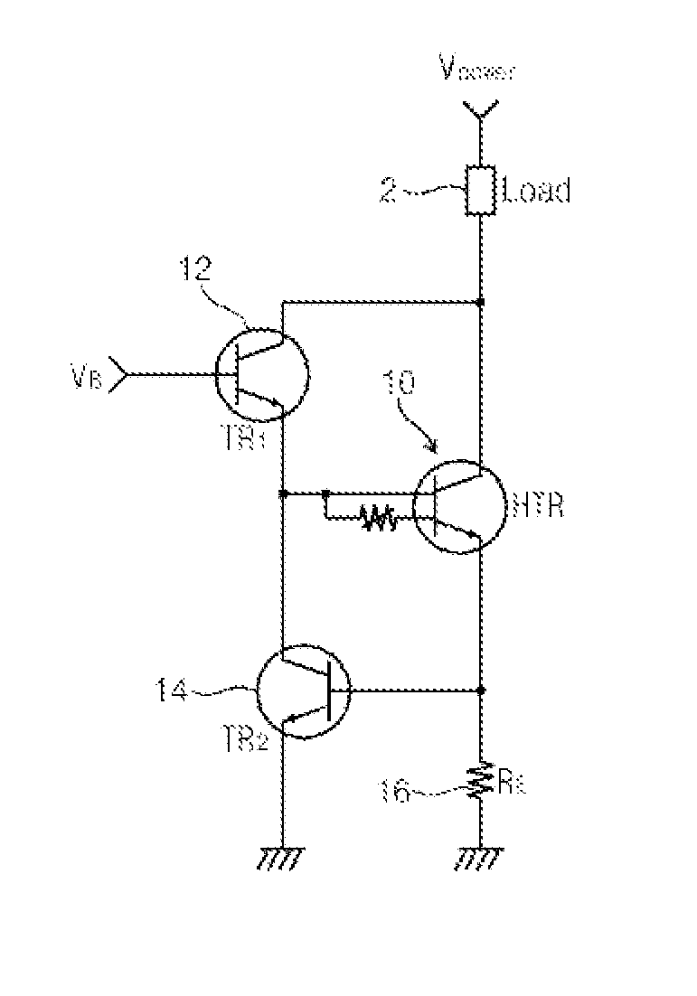
The patent text describes a constant current circuit and a method of driving it. The circuit includes a power supply, a load, a heat control portion, a first transistor, and a second transistor. The heat control portion suppresses the thermal runaway phenomenon of semiconductor, the first transistor increases the efficiency of the heat control portion, and the second transistor maintains a constant current flow to the ground connection resistor. The method involves applying the power supply voltage, applying a common load voltage to the heat control transistor and the first transistor, applying a base voltage to the first transistor, and using the second transistor to flow the current to the ground when the voltage between the heat control transistor and the resistor reaches a predetermined level. The technical effect of this invention is to provide a circuit that can maintain a constant current flow to the load, even when the load voltage varies.

Problems solved by technology

Since this constant current circuit should include a comparator, the constant current circuit has a complicated structure and is expensive.
If large currents flow through the constant current circuit like that, a thermal runaway occurs in a semiconductor device itself.
Thus, that constant current circuit is not suitable as a constant current circuit through which relatively large currents flow.
However, when designing a constant current circuit using a bipolar transistor, a current may be inefficiently wasted.

Method used


Image

  • Constant current circuit of high efficiency
  • Constant current circuit of high efficiency
  • Constant current circuit of high efficiency

Examples


Embodiment Construction

[0025]Embodiments of inventive concepts will be described more fully hereinafter with reference to the accompanying drawings, in which embodiments of the invention are shown. This inventive concept may, however, be embodied in many different forms and should not be construed as limited to the embodiments set forth herein. Rather, these embodiments are provided so that this disclosure will be thorough and complete, and will fully convey the scope of the inventive concept to those skilled in the art. In the drawings, the size and relative sizes of layers and regions may be exaggerated for clarity. Like numbers refer to like elements throughout.

[0026]It will be understood that when an element is referred to as being “connected” or “coupled” to another element, it can be directly connected or coupled to the other element or intervening elements may be present.

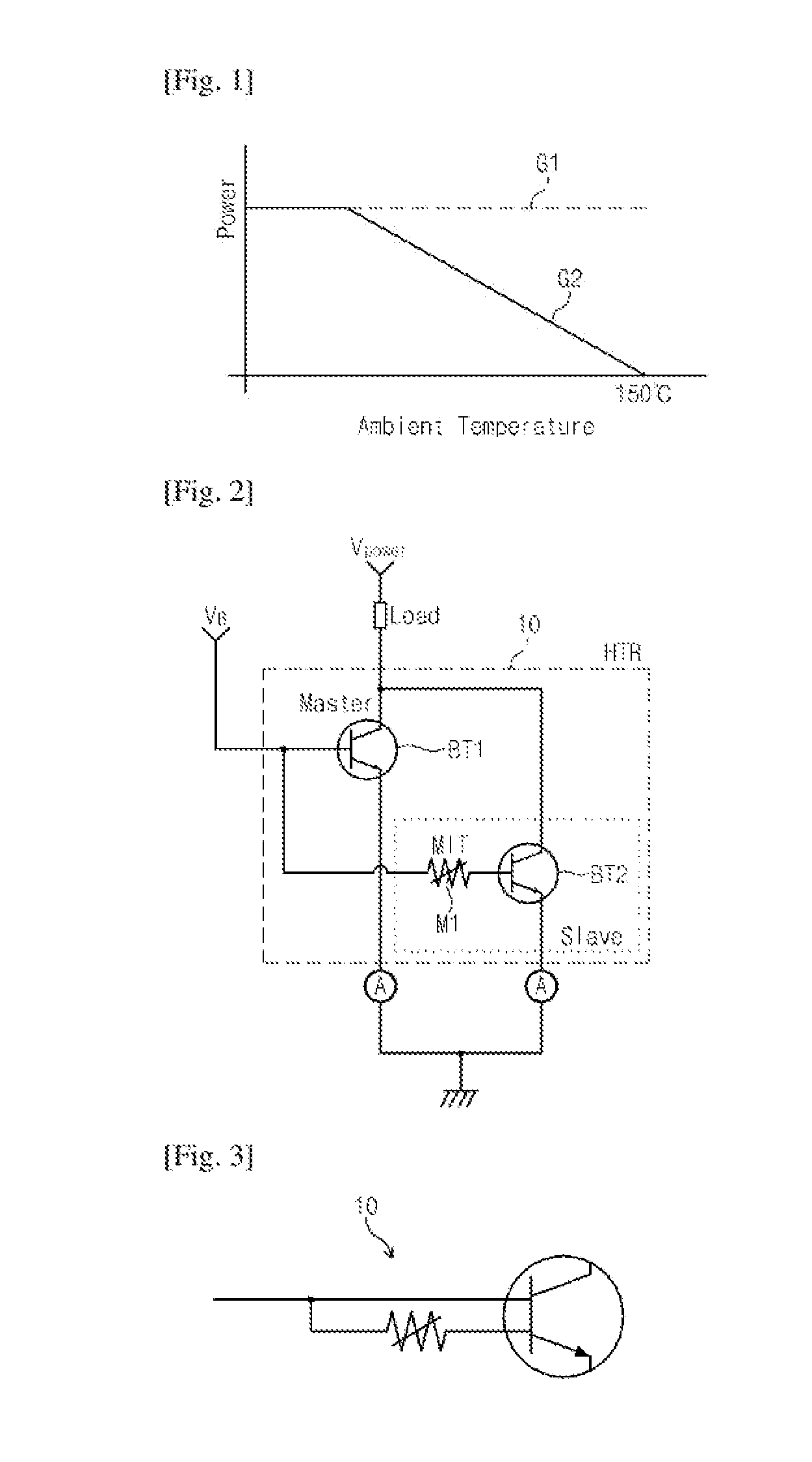
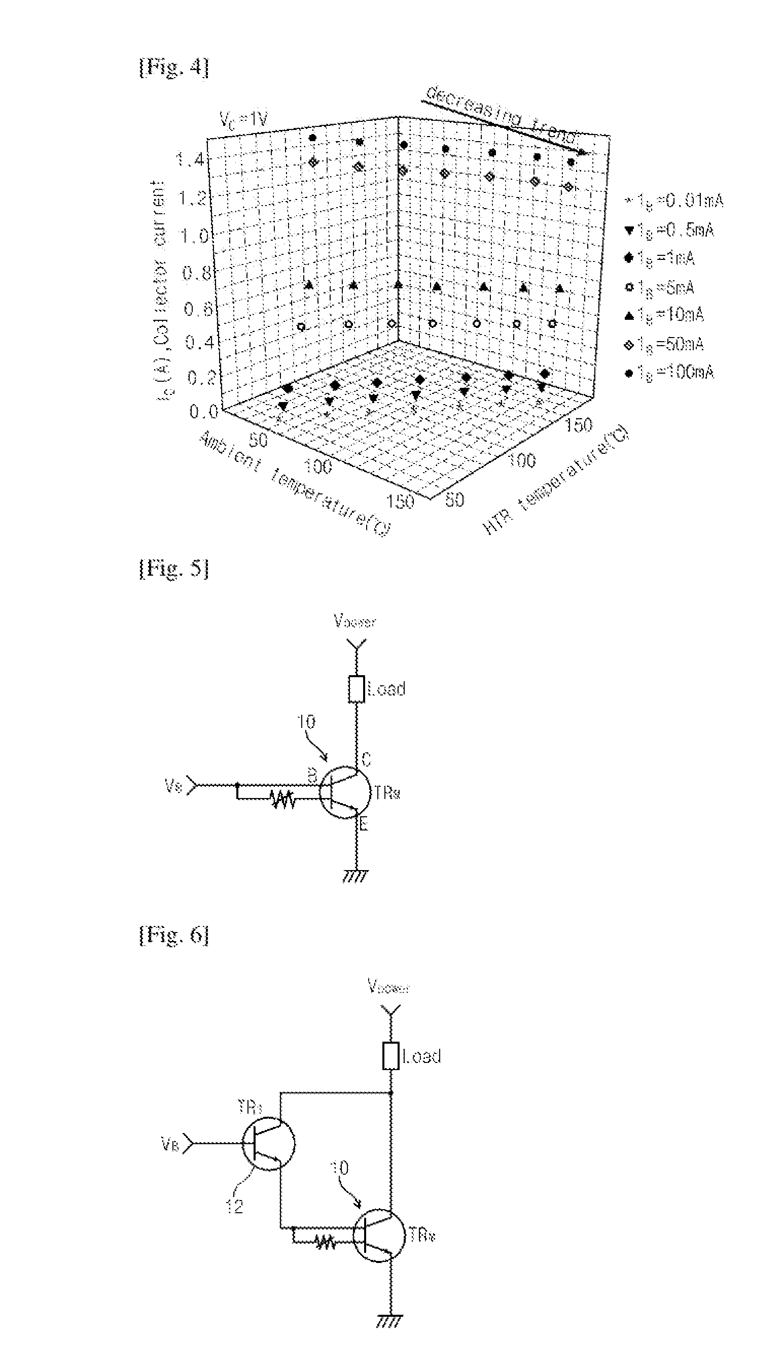
[0027]FIG. 1 is a graph showing a characteristic of a power relative to a temperature of a transistor. In the graph, a horizontal...


PUM


Abstract

The present inventive concept is a hyuntak transistor that can prevent a thermal runaway phenomenon and a low heat high efficiency constant current circuit using an auxiliary transistor capable of a high amplification and a constant current. The circuit may be applied to drive a LED and a motor.

Description

TECHNICAL FIELD[0001]The present inventive concept herein relates to circuits of electronic device, and more particularly, to a constant current circuit of high efficiency.BACKGROUND ART[0002]In general, when a current flows through a bipolar transistor, Joule's heat is produced and an electrical resistance of semiconductor device is reduced by the produced Joule's heat. Accordingly, larger currents flow through a bipolar transistor and more Joule's heat are produced. If this process is repeated, very large currents flow through a bipolar transistor and a power characteristic of bipolar transistor is degraded by the produced Joule's heat.[0003]A bipolar transistor may be destroyed by more Joule's heat and this phenomenon is called a thermal runaway. A solution to prevent that thermal runaway is that a constant current flows through a bipolar transistor or a semiconductor transistor.[0004]A well known constant current circuit essentially includes a comparator comparing a feedback cur...

Claims


Application Information

Patent Timeline
IPC IPC(8): G05F3/02
CPCG05F3/02G05F3/16H02M1/327H02H9/02
Inventor KIM, HYUN-TAKKIM, BONGJUNKWAG, SUN SHINKIM, JUN SIK
Owner ELECTRONICS & TELECOMM RES INST
Learn More