
Device and method for automatically laterally storing a motor vehicle in a storing device

Inactive Publication Date: 2013-10-24
SERVA TRANSPORT SYST
View PDF21 Cites 131 Cited by
  • Summary
  • Abstract
  • Description
  • Claims
  • Application Information

AI Technical Summary

Benefits of technology

The invention allows for efficient storage of automotive vehicles by optimizing the surface area when storing them in rows of different sizes. This results in a minimum spacing between the vehicles, which takes into account the different vehicle lengths. Additionally, the invention utilizes driverless transporting means for parallel operation in the automatic parking system. This eliminates the need for guides on the ground, making the system more flexible.

Problems solved by technology

It proves to be difficult to lift and to transport vehicles from a parking area since the ground clearance of vehicles only makes available a small space for transport machines.
This makes parking with an automatic system difficult and leads to a multi-storey car park which is not utilised efficiently since the markedly different vehicles are parked on parking spaces of the same size.
Therefore, this is not applied in known automatic parking systems since problems with respect to construction technology make it impossible to design the receiving trucks to be so small that they can park vehicles precisely bumper to bumper.
Since the vehicle sizes vary so greatly, it is therefore also impossible with this solution to park vehicles really efficiently.
A further problem of the currently known automatic car parks is that a machine unit in one system section is responsible for approx.
This means that, in the case of a system failure, a parked vehicle in the corresponding area of responsibility of the machine cannot be accessed since either the pallet, the vehicle receiving mechanisms or the conveying lift blocks the system.
Furthermore, it is not possible in the case of known automatic car parks that a plurality of pallets or vehicle receiving mechanisms work together in parallel operation in the same system section if for example a plurality of vehicles is requested at the same time from the same system section.
The vehicles cannot therefore be retrieved in parallel as fast as possible.
This is not possible since the machines are constructionally tied to their position, i.e. generally by a linear guide.
In the case of known automatic parking garages, vehicles cannot be retrieved manually in the case of complete plant failure.
Known parking systems also cannot be incorporated in already existing multi-storey car parks without great constructional complexity.
In the case of the known systems, no significantly improved degree of surface utilisation is achieved even with complex conversion of a traditional car park into an automatic car park since the vehicles—as explained already—cannot be parked corresponding to their size.
Furthermore, no communication between customer and the parking system takes place with currently known parking systems.
It is difficult with this type of conveying means to park a plurality of vehicles adjacently in the transverse direction since the gripping arms, in the case of three parallel-parked vehicles, would have to extend approx.
It is also difficult with gripping arms which are far extended to absorb the load caused by the received vehicle at the end of the telescope-like gripping arms.

Method used


Image

  • Device and method for automatically laterally storing a motor vehicle in a storing device
  • Device and method for automatically laterally storing a motor vehicle in a storing device
  • Device and method for automatically laterally storing a motor vehicle in a storing device

Examples


Embodiment Construction

[0018]An embodiment of the invention is explained in more detail with reference to the drawing. There are shown:

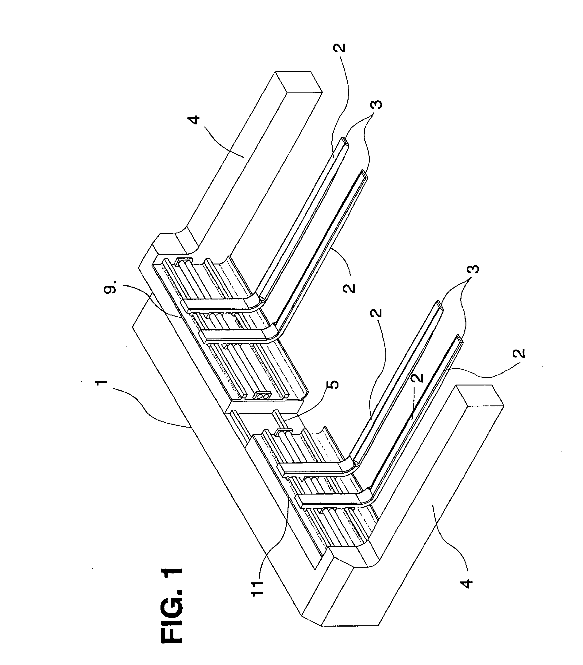
[0019]FIG. 1: A plan view of the surface-maneuverable driverless transporting means

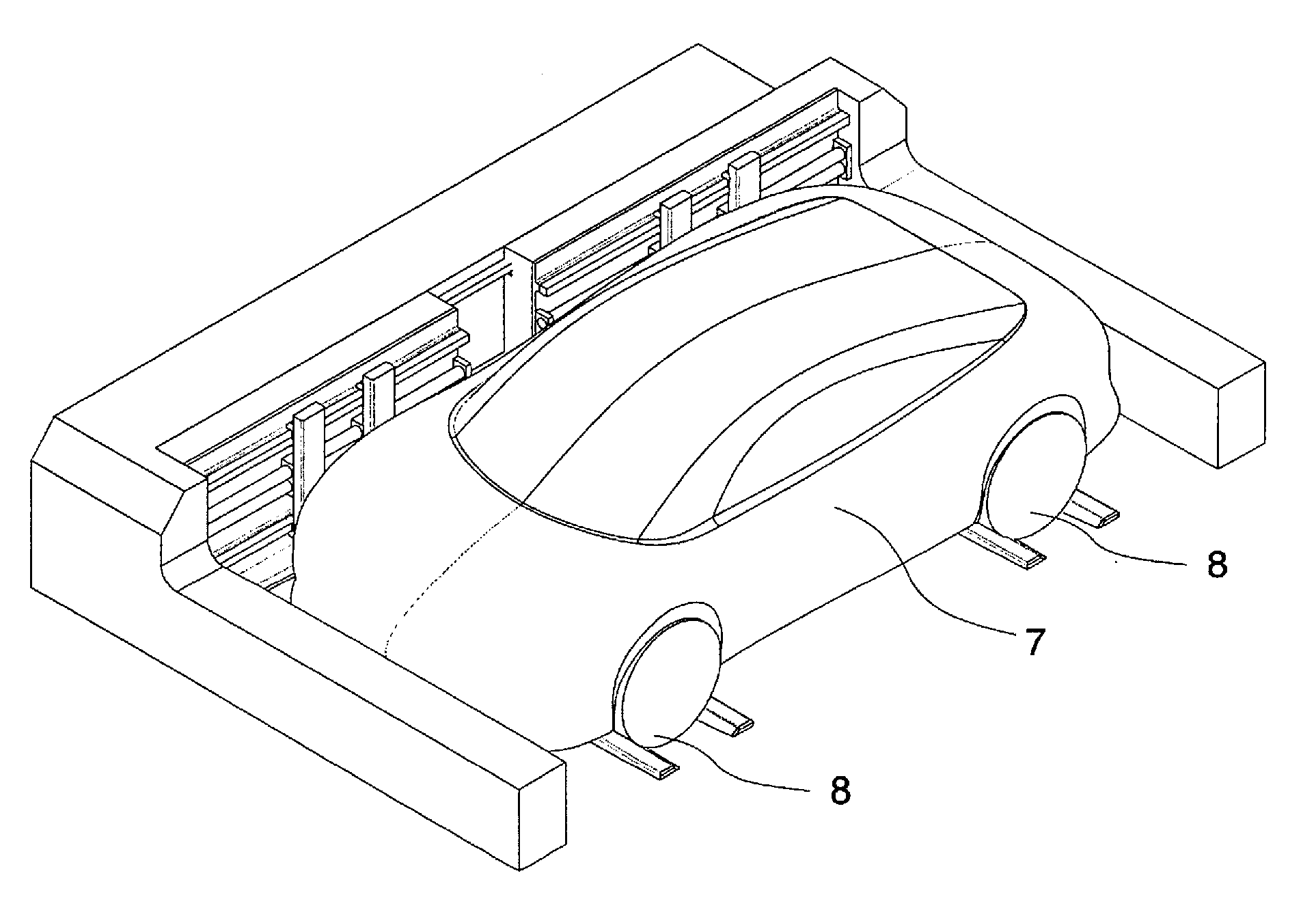
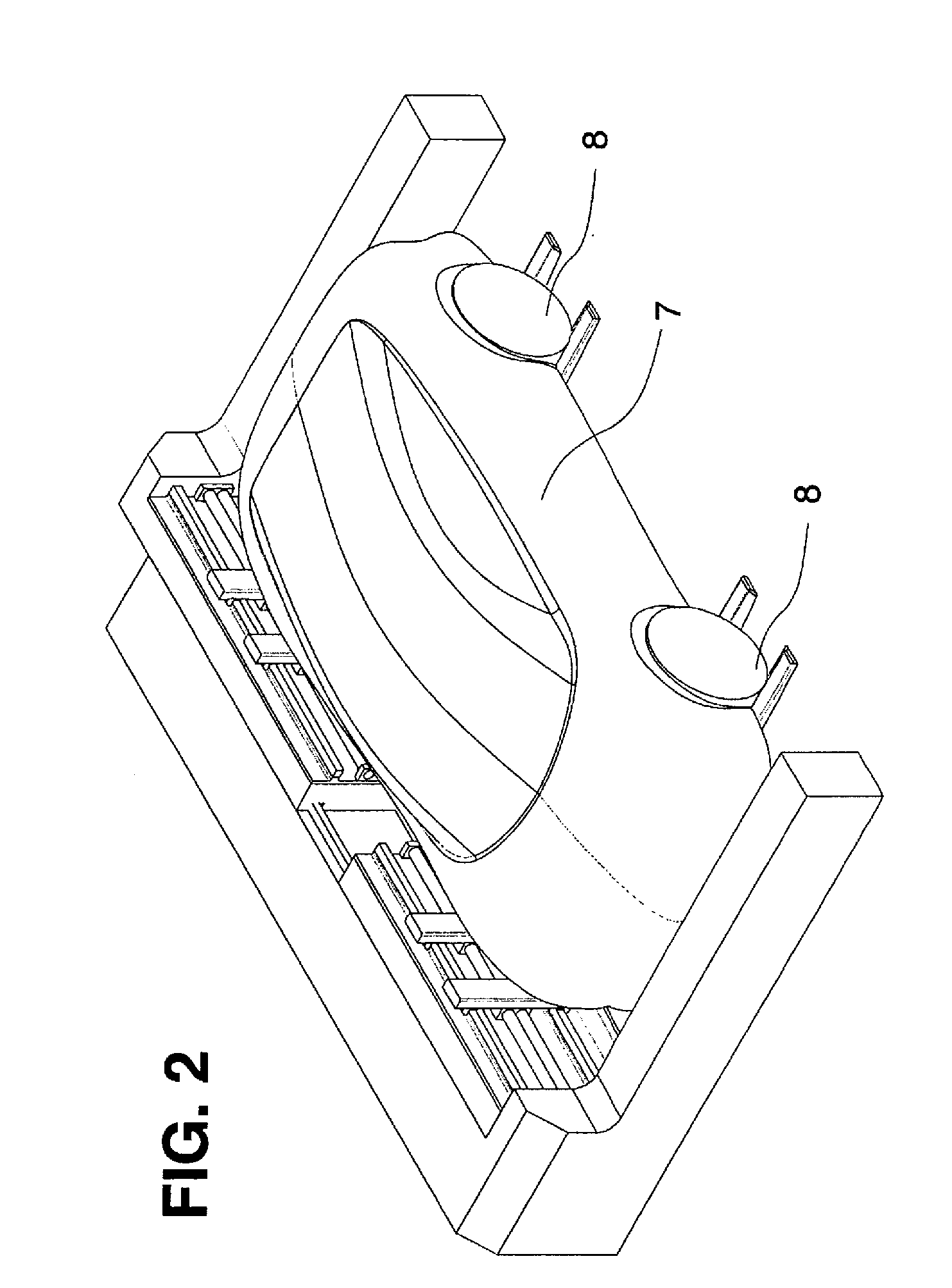
[0020]FIG. 2: A plan view of the surface-maneuverable driverless transporting means with a received automotive vehicle

[0021]FIG. 3: A plan view of the transfer station

[0022]FIG. 4: A plan view of the storage facility

[0023]FIG. 5: A plan view of the surface-maneuverable transporting means with a beam as device for length adjustment

[0024]The surface-maneuverable driverless transporting means (1), represented in FIGS. 1 to 3, has, at its ends which are parallel next to the pairs of forks (3), surface-maneuverable supports (4), which, in addition to the transporting means, absorb a part of the load caused by the automotive vehicle (7) and prevent tilting. The pairs of forks (3) are mounted, on one side, on the surface-maneuverable driverless transporting means (1) and can be displaced individual...


PUM


Abstract

Device for storing an automotive vehicle transversely relative to its longitudinal axis on a parking space of a storage facility, having a surface-maneuverable, driverless transporting means which is disposed parallel to the longitudinal axis of the automotive vehicle when receiving the automotive vehicle and has horizontally extending pairs of forks which are disposed thereon at one side and perpendicularly, the forks of the pairs of forks being displaceable individually horizontally along the transporting means and the pairs of forks moving under wheels respectively of a vehicle axle from one side of the automotive vehicle in order to grip the wheels by displacing the individual forks horizontally towards each other, whereupon the automotive vehicle is lifted for transporting, surface-maneuverable supports (4) being disposed on the transporting means (1) respectively at the end-side, which supports extend horizontally and parallel to the pairs of forks (3) and, when the pairs of forks (3) move under the wheels (8), move past the automotive vehicle (7) at the front- and rear-side at a small spacing, the spacing between the supports (4) being adjustable, a measuring device (6), before the automotive vehicle (7) is received, determining its length, axle positions and the position of the automotive vehicle (7) in space, the surface-maneuverable, driverless transporting means (1) adapting, with the data transmitted from the measuring device (6), its length determined by the spacing of the supports (4) and the position of the pairs of forks (3) automatically to the dimensions of the automotive vehicle (7) to be received, and the load absorbed upon lifting the automotive vehicle (7) being transmitted, on the one hand, by the transporting means (1) and, on the other hand, by the surface-maneuverable supports (4) to the travel surface.

Description

PRIORITY INFORMATION[0001]The present invention is a 371 National Phase Application of PCT / EP2011 / 005983, filed on Nov. 29, 2011 that claims priority to German Application No. 102010052850.1 filed on Nov. 29, 2010, which are incorporated herein by reference in their entireties.BACKGROUND OF THE INVENTION[0002]The invention relates to a device and a method for automatic storage of an automotive vehicle transversely relative to its longitudinal axis on a parking space of a storage facility.[0003]In the case of known automatic multi-storey car parks, transport robots installed in a fixed manner or systems based on pallets are used in order to park vehicles automatically. It proves to be difficult to lift and to transport vehicles from a parking area since the ground clearance of vehicles only makes available a small space for transport machines. The most varied of vehicle sizes are found in current road traffic: small cars with a very small wheelbase but also vehicles, such as for exam...

Claims


Application Information

Patent Timeline
IPC IPC(8): E04H6/30
CPCE04H6/305E04H6/183
Inventor MEIRER, LEOPOLDKOCH, RUPERTBELLAFLOR, CARY TOMAS
Owner SERVA TRANSPORT SYST
Learn More