
Antenna system to control RF radiation exposure

a technology of radiation exposure and antenna system, which is applied in the direction of antennas, transmission, modulation, etc., can solve the problems of reducing affecting the service life of the antenna system, and affecting the operation of the antenna system

Active Publication Date: 2013-10-24
FASMETRICS LTD
View PDF3 Cites 33 Cited by
  • Summary
  • Abstract
  • Description
  • Claims
  • Application Information

AI Technical Summary

Benefits of technology

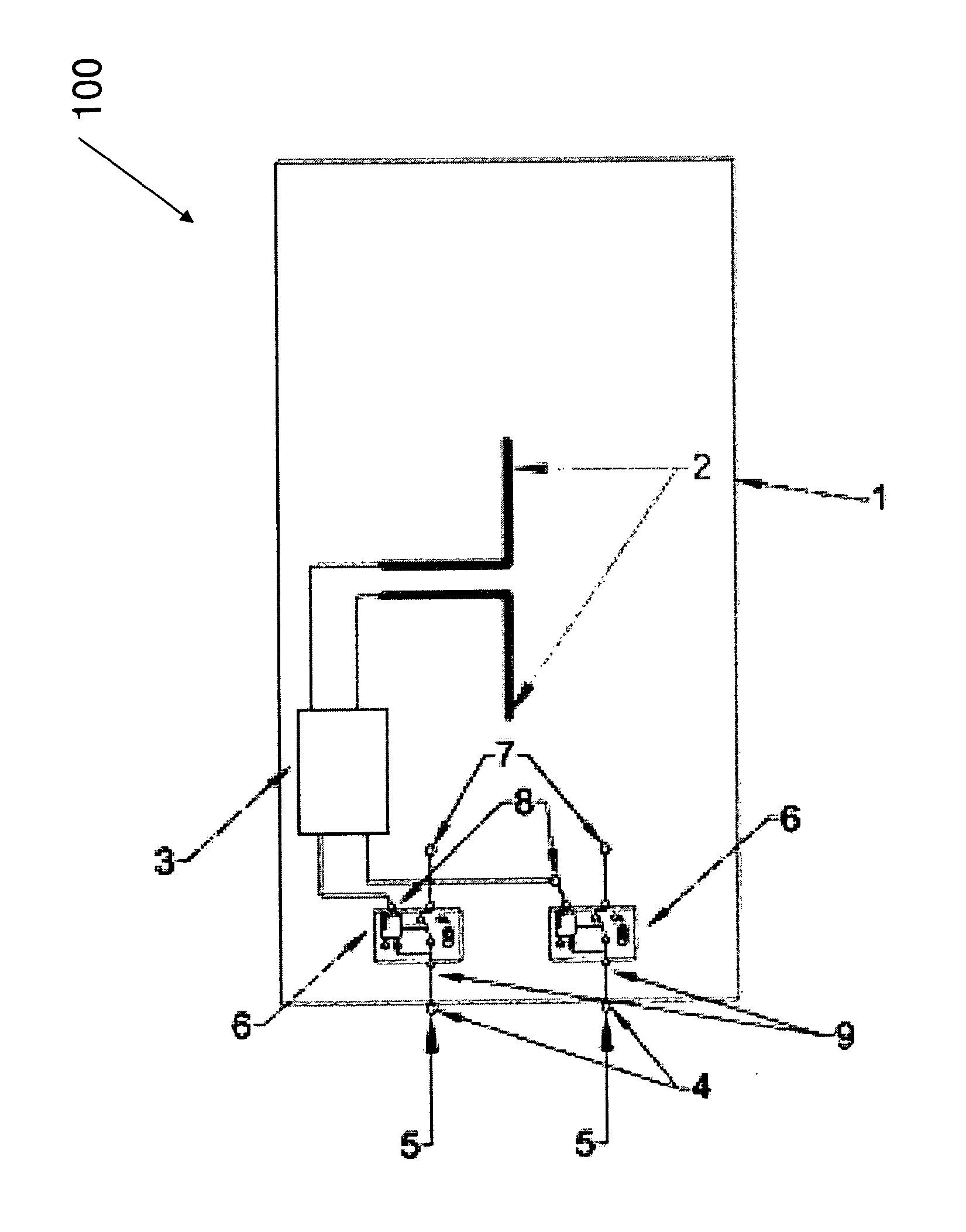
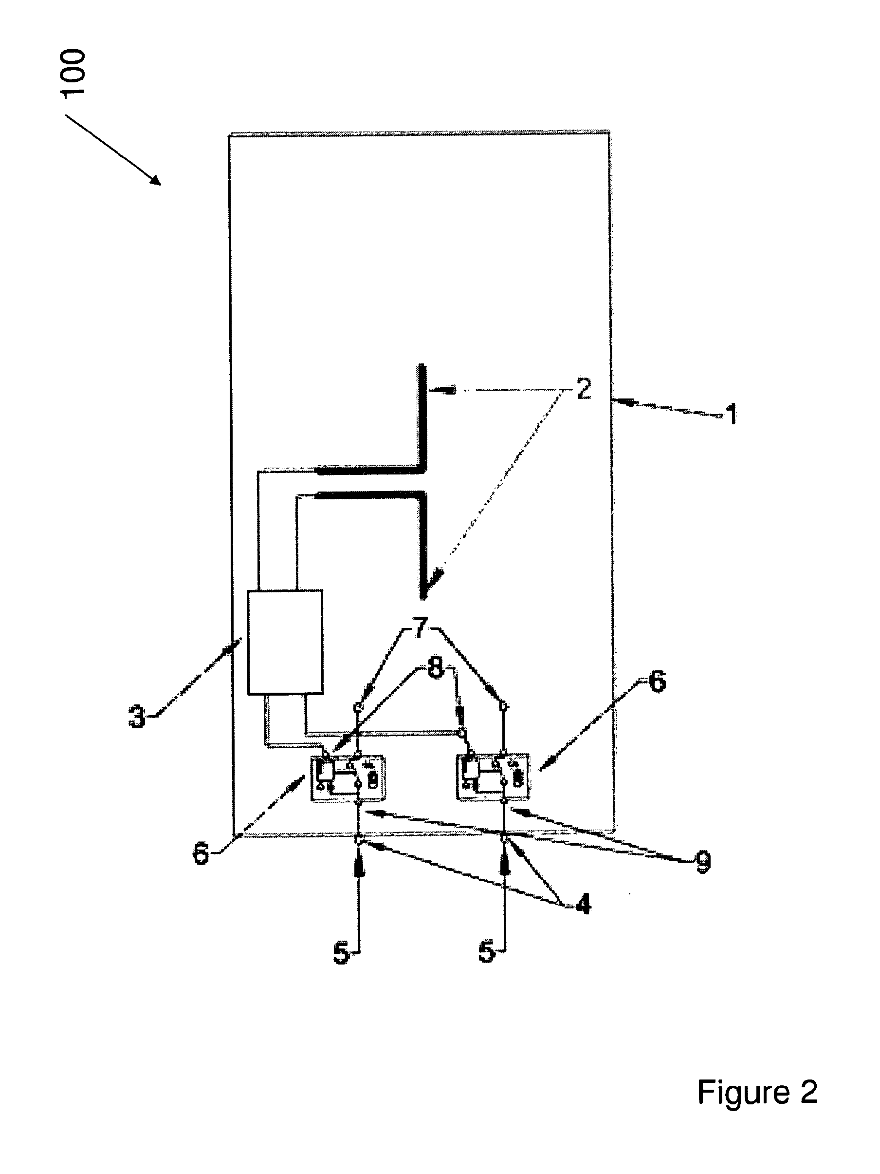
The invention is an antenna system that can automatically measure and control the amount of RF radiation emitted by the antenna. This system uses a sensor to measure the strength of the RF radiation, and a processor to determine the amount of power supplied to the antenna. The control circuitry can selectively vary or disengage the power supplied to the antenna based on the measured strength of the RF radiation. This system allows for real-time monitoring and control of RF radiation exposure, ensuring that the antenna complies with regulatory standards. It can also be used in multichannel and broadband mobile communication networks to automatically regulate the input RF power to the antenna. Overall, this invention provides a built-in measurement and control system for RF radiation emitted from the antenna, allowing for efficient and effective control of RF radiation exposure.

Problems solved by technology

The control of the electromagnetic environment is a difficult task that depends on a number of parameters.
One problem faced by both the general public and public authorities is the difficulty of continuously measuring the RF emissions at any distance away from a given mobile communication antenna.
As a result, since the electromagnetic environment cannot be continuously verified everywhere, the general public (and, in some instances) the authorities come in direct conflict with mobile network operators resulting in the delaying or even blocking of investments on such antenna systems that intend to be installed in residential and workplace areas, for example.
It is also known that the size of measurement devices placed on, or near, an antenna may adversely affect the performance of the antenna.
Such a reduction in performance is undesirable.

Method used


Image

  • Antenna system to control RF radiation exposure
  • Antenna system to control RF radiation exposure
  • Antenna system to control RF radiation exposure

Examples


Embodiment Construction

[0032]It is well known that in free space, all electromagnetic waves (radio, light, X-rays, etc.) obey the inverse-square law which states that the power density of an electromagnetic wave is proportional to the inverse of the square of the distance from the source.

[0033]Doubling the distance from a transmitter means that the power density of the radiated wave at that new location is reduced to one-quarter of its previous value. The power density per surface unit is proportional to the product of the electric and magnetic field strengths. Thus, doubling the propagation path distance from the transmitter reduces each of their received field strengths over a free-space path by one-half. As a result, measuring the electromagnetic wave directly at the source provides valuable information relevant to the calculation of the strength of radiation at any distance away from the source. For known propagation environments, the power density of the electromagnetic wave can be known.

[0034]The an...


PUM


Abstract

An antenna measurement and control system for use with a transmitting antenna, the system comprising a sensor configured to determine an indication of the radiation emitted by the antenna; control circuitry connectable to the antenna and configured to selectively vary, or disengage, the power supplied to the antenna, and a processor connectable to the sensor and control circuitry, wherein the processor is configured to control the control circuitry in response to the determined indication of the emitted radiation.

Description

FIELD OF THE INVENTION[0001]The invention relates to installations for antenna systems, in particular those installed in urban areas. In particular the invention relates to an apparatus and method for determining a value of RF power which is indicative of the RF power emitted by the antenna and adjusting the amount of power emitted by the antenna in response to the determined value of RF power.BACKGROUND[0002]Monitoring of the electromagnetic (EM) field environment surrounding antennas is desirable because regulations exist which stipulate maximum radiation emissions to which humans should be exposed. Measurement devices that can monitor electromagnetic field strength are commercially available and generally known in the art. Such monitoring devices may provide accurate (on the spot) measurements of electromagnetic fields.[0003]The installation of mobile communication antenna systems is prevalent in many urban areas due to the increase in use of mobile telephones and the like. The i...

Claims


Application Information

Patent Timeline
Patent Type & Authority Applications(United States)
IPC IPC(8): H01Q1/24
CPCH01Q1/24H01Q1/246H04B17/101
Inventor KOLOKOTRONIS, DIMITRIS
Owner FASMETRICS LTD
Learn More