
Sheet conveyance apparatus and image forming apparatus

a technology of conveyancing apparatus and sheet, applied in the direction of registering device, thin material handling, article separation, etc., can solve the problems of limiting the speed (time), deteriorating the performance of sheet skew correction, and formation of defective images, so as to improve productivity and skew correction performance, the effect of higher accuracy

Active Publication Date: 2013-10-31
CANON KK
View PDF7 Cites 7 Cited by
  • Summary
  • Abstract
  • Description
  • Claims
  • Application Information

AI Technical Summary

Benefits of technology

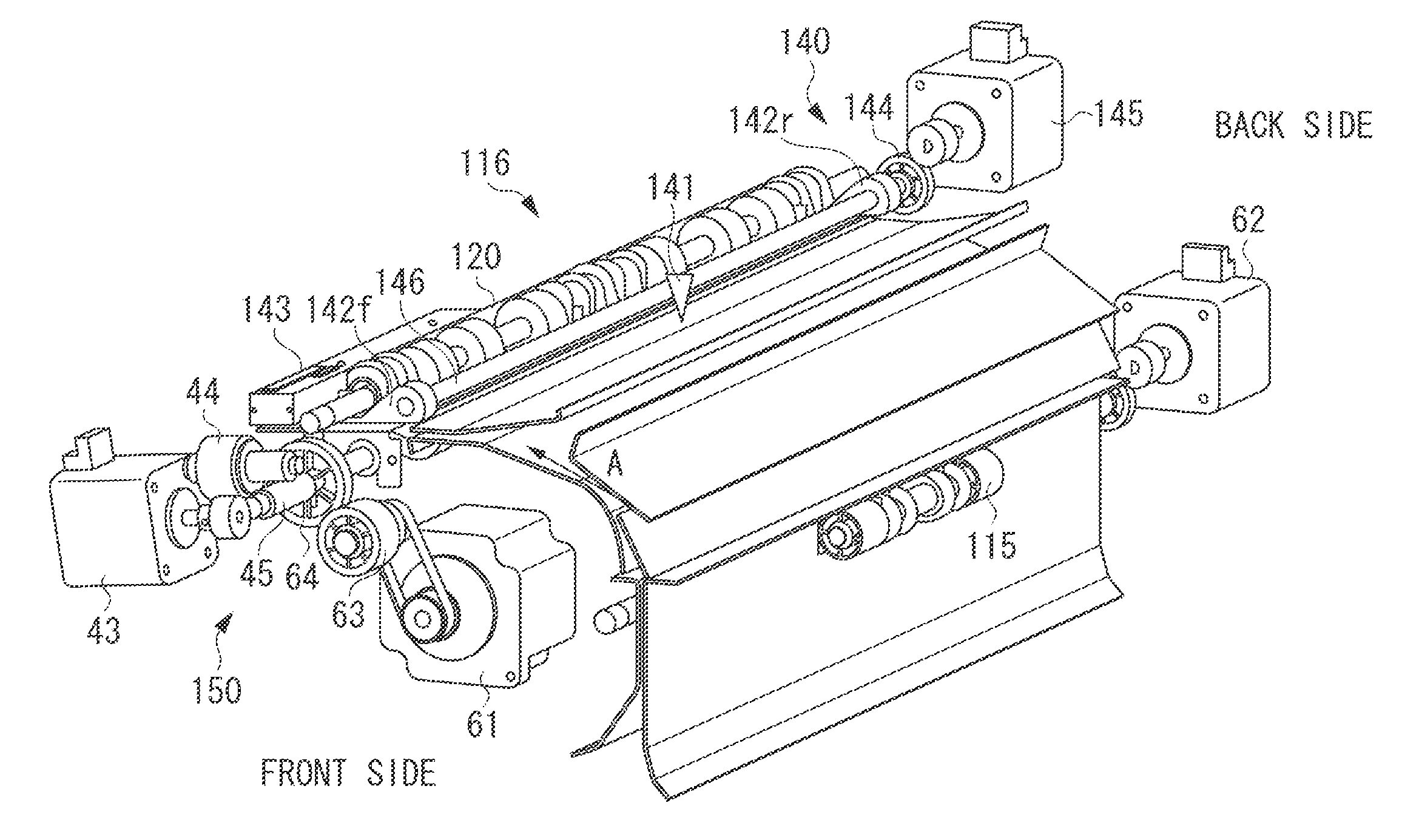
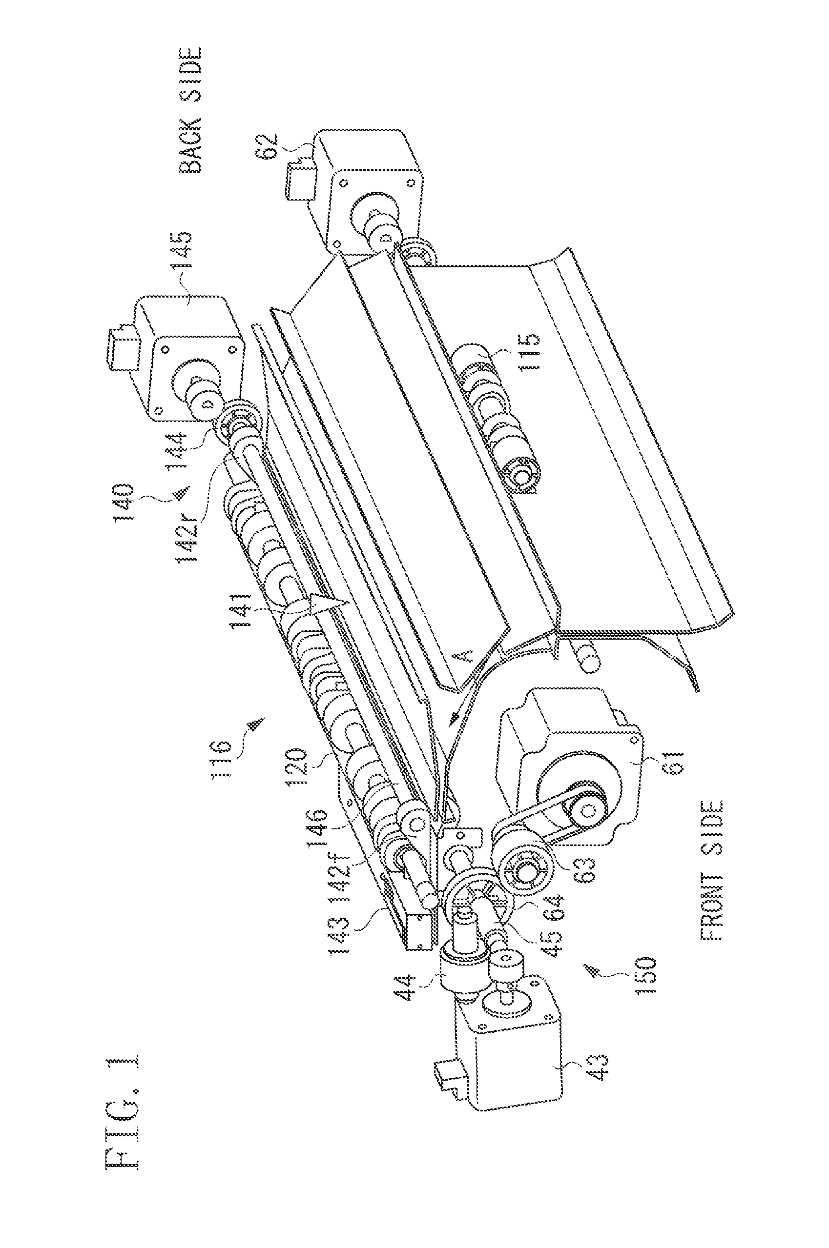
The present invention is related to a sheet conveyance apparatus that improves productivity and skew correction performance during image transfer. This is achieved by setting a separated state of the registration roller pair, which helps convey sheets with higher accuracy. After stopping a sheet at a stop position, a control unit rotates the registration roller pair backward so that the leading edge of the sheet can reliably contact the nip portion of the registration roller pair. This ensures that even when the interval between preceding and succeeding sheets becomes shorter, skewing of the sheet can be corrected, and productivity and skew correction performance can be improved.

Problems solved by technology

The following problems occur in the configuration where both the operation of stopping the sheet immediately before the nip portion of the registration roller pair and the operation of setting the registration roller pair to the separated state and the press-contact state are carried out.
On the other hand, there is a limit to a speed (time) for setting the registration roller pair to the press-contact state.
This greatly deteriorates sheet skew correction performance.
The deteriorated sheet skew correction performance causes formation of a defective image because the image cannot be formed in a normal position of the sheet.
However, when the stop position is set more upstream in the conveying direction, much time is necessary for operations to resume the rotation of the upstream roller pair, convey the sheet at a low speed, and form a loop, consequently lowering productivity.

Method used


Image

  • Sheet conveyance apparatus and image forming apparatus
  • Sheet conveyance apparatus and image forming apparatus
  • Sheet conveyance apparatus and image forming apparatus

Examples


Embodiment Construction

[0027]Various exemplary embodiments, features, and aspects of the invention will be described in detail below with reference to the drawings.

[0028]FIG. 7 is a schematic sectional view illustrating a color digital printer as an example of an image forming apparatus to which a sheet conveyance apparatus according to an exemplary embodiment.

[0029]First, an image forming unit will be described. Surfaces of four photosensitive drums 101a to 101d are uniformly charged by charging rollers 102a to 102d. Laser scanners 103a to 103d, to which image signals of yellow (Y), magenta (M), cyan (C), and black (K) are respectively input, irradiate the drum surfaces with laser beams according to the image signals, and neutralize charges to form latent images.

[0030]The latent images formed on the photosensitive drums are developed by toner of yellow, magenta, cyan, and black by developing devices 104a to 104d. The toner developed on the photosensitive drums is sequentially transferred to an intermedia...


PUM


Abstract

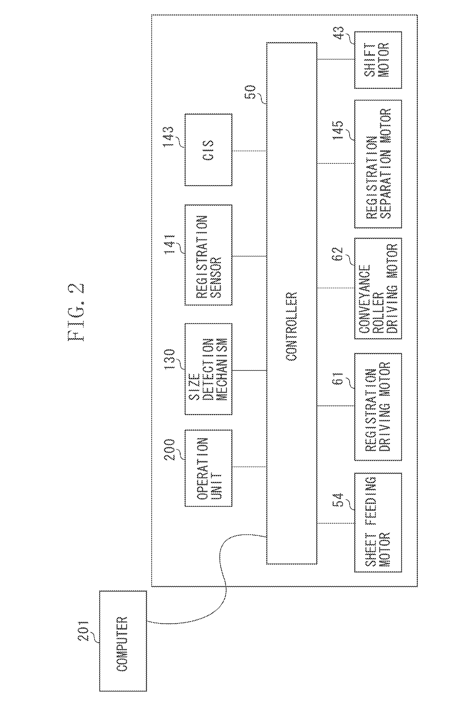
A sheet conveyance apparatus includes a conveyance roller pair, a conveyance roller driving unit, a registration roller pair, a registration driving unit, a separation and press-contact unit configured to set the registration roller pair to a separated state and to a press-contact state, and a control unit. After a sheet has stopped at a stop position immediately before the registration roller pair, the registration roller pair having been set to the separated state is set to the press-contact state. The registration roller pair is rotated backward during formation of a loop in the sheet.

Description

BACKGROUND[0001]1. Field[0002]Aspects of the present invention generally relate to a sheet conveyance apparatus that corrects skewing of a sheet, and an image forming apparatus that includes the sheet conveyance apparatus.[0003]2. Description of the Related Art[0004]A conventional image forming apparatus for forming an image on a sheet includes, in order to form an image on a sheet without any inclination, a skew correction device that corrects skewing of a sheet fed to an image forming unit.[0005]Japanese Patent No. 4016621 discusses a skew correction device that corrects skewing of the leading edge of a sheet by causing the leading edge of the sheet conveyed by an upper roller pair disposed upstream of a registration roller pair to contact the nip portion of the registration roller pair and forming a loop on the sheet.[0006]Japanese Patent Application Laid-Open No. 6-127753 discusses a skew correction device that corrects skewing by stopping a sheet conveyed by an upstream roller ...

Claims


Application Information

Patent Timeline
IPC IPC(8): B65H7/00
CPCB65H7/00B65H7/08B65H7/10B65H9/008B65H2404/1424B65H2511/224B65H2513/11B65H2513/41B65H2701/1311B65H2220/01B65H2220/02B65H2220/11
Inventor DENO, KOUHEI
Owner CANON KK
Learn More