
Electrically conductive roller

Inactive Publication Date: 2013-10-31
SUMITOMO RUBBER IND LTD
View PDF2 Cites 10 Cited by
  • Summary
  • Abstract
  • Description
  • Claims
  • Application Information

AI Technical Summary

Benefits of technology

The present invention provides an electrically conductive roller that has stable resistance against environmental conditions and is less likely to contaminate the photoreceptor. The roller has high resistance to environmental factors and is less influenced by changes in environmental conditions. This results in consistent and reliable performance.

Problems solved by technology

However, the lithium salt is highly hygroscopic and deliquescent and, therefore, is liable to absorb moisture to suffer from a change in weight or deliquesce during weighing thereof.
This makes it difficult to accurately weigh the lithium salt.
In addition, the change in weight due to the moisture absorption is often influenced by the environmental conditions (particularly the humidity and the temperature) to suffer from batch-to-batch variations when the electrically conductive rubber composition is prepared by adding the lithium salt.
Further, the electrically conductive roller including the roller body containing the lithium salt is liable to be influenced by the environmental conditions (particularly the humidity) even after the production thereof to suffer from a change in roller resistance due to the moisture absorption, and the change in roller resistance is significant.
This may result in significant variations, for example, in the image density of the entire formed image.
In addition, the electrically conductive roller serving as the charging roller is liable to cause streaking in the formed image, for example, when the operation of the image forming apparatus is restarted after being once stopped with the electrically conductive roller in direct contact with the surface of the photoreceptor, particularly in a higher temperature / higher humidity environment.
That is, the electrically conductive roller is liable to absorb a greater amount of moisture, particularly in the higher temperature / higher humidity environment, and the moisture contaminates a linear region of the surface of the photoreceptor in contact with the charging roller during the stop of the image forming apparatus to locally reduce the resistance of the region.

Method used


Image

  • Electrically conductive roller
  • Electrically conductive roller

Examples


example 1

[0125]A base polymer was prepared by blending 60 parts by mass of ECO (EPICHLOMER (registered trade name) D available from Daiso Co., Ltd. and having an ethylene oxide content of 61 mol %) as the epichlorohydrin rubber E, and 10 parts by mass of CR(SHOPRENE (registered trade name) WRT available from Showa Denko K.K.) and 30 parts by mass of NBR (JSR N250 SL (lower-acrylonitrile-content NBR having an acrylonitrile content of 20%) available from JSR Co., Ltd) as the diene rubber N. While the base polymer was kneaded by means of a 9L kneader, 2.5 parts by mass of potassium bis(trifluoromethanesulfonyl)imide ((CF3SO2)2NK EF-N112, K-TFSI available from Mitsubishi Materials Electronic Chemicals Co., Ltd.) as the potassium salt and ingredients shown below in Table 1 were added to and kneaded with the base polymer. Thus, an electrically conductive rubber composition was prepared.

[0126]The mass ratio E / N between the epichlorohydrin rubber E and the diene rubber N was E / N=60 / 40.

TABLE 1Ingredi...

example 2

[0132]An electrically conductive rubber composition was prepared in substantially the same manner as in Example 1, except that 2.5 parts by mass of potassium bis(fluorosulfonyl)imide ((FO2S)2NK) K-FSI available from Mitsubishi Materials Electronic Chemicals Co., Ltd.) was blended as the potassium salt. Then, an electrically conductive roller was produced by using the electrically conductive rubber composition thus prepared. The mass ratio E / N between the epichlorohydrin rubber E and the diene rubber N was E / N=60 / 40.

examples 3 and 4

[0133]Electrically conductive rubber compositions were prepared in substantially the same manners as in Examples 1 and 2, except that the CR was not blended as the diene rubber N of the base polymer and the proportion of the NBR was 40 parts by mass. Then, electrically conductive rollers were produced by using the electrically conductive rubber compositions thus prepared. The mass ratio E / N between the epichlorohydrin rubber E and the diene rubber N was E / N=60 / 40.


PUM


Abstract

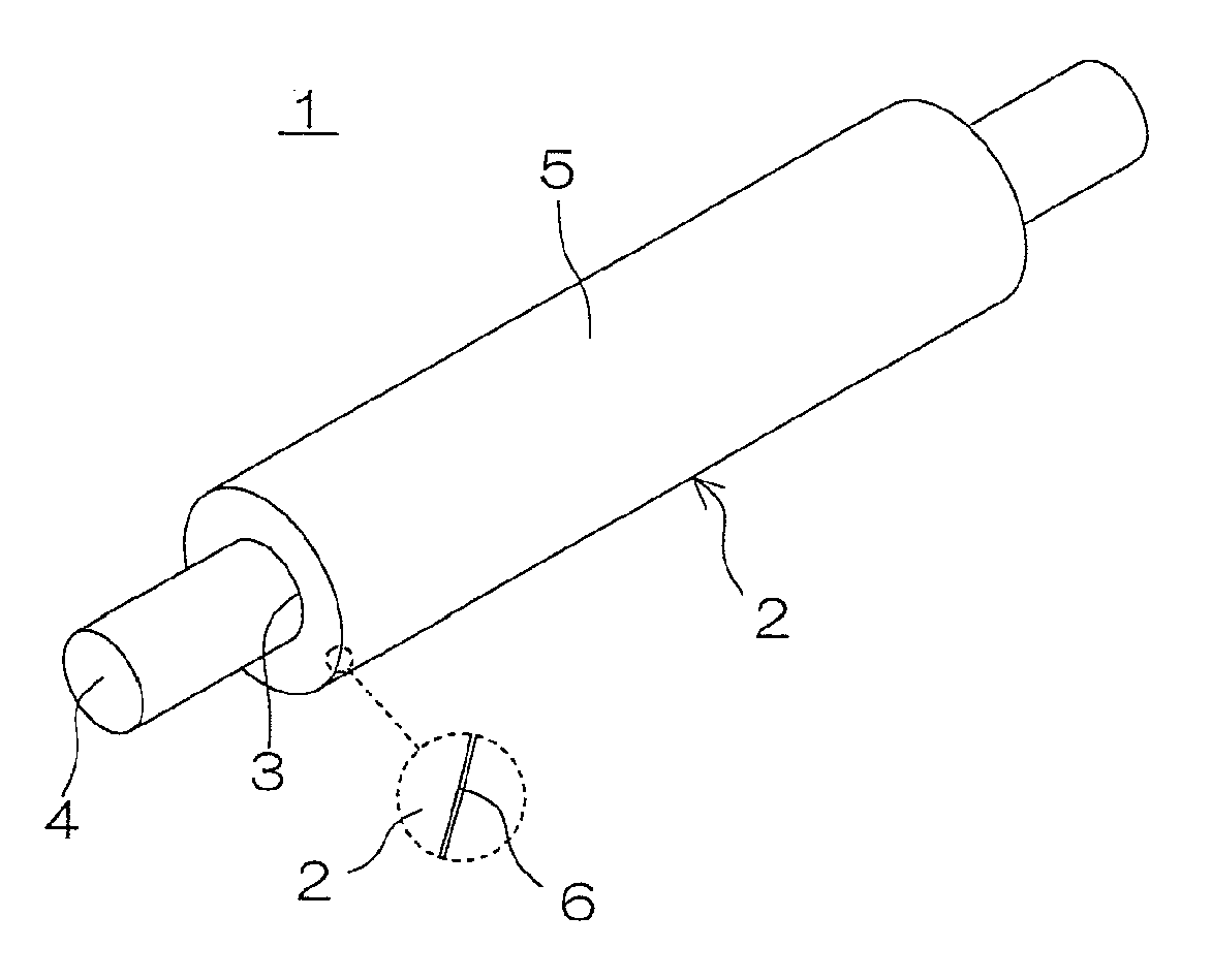
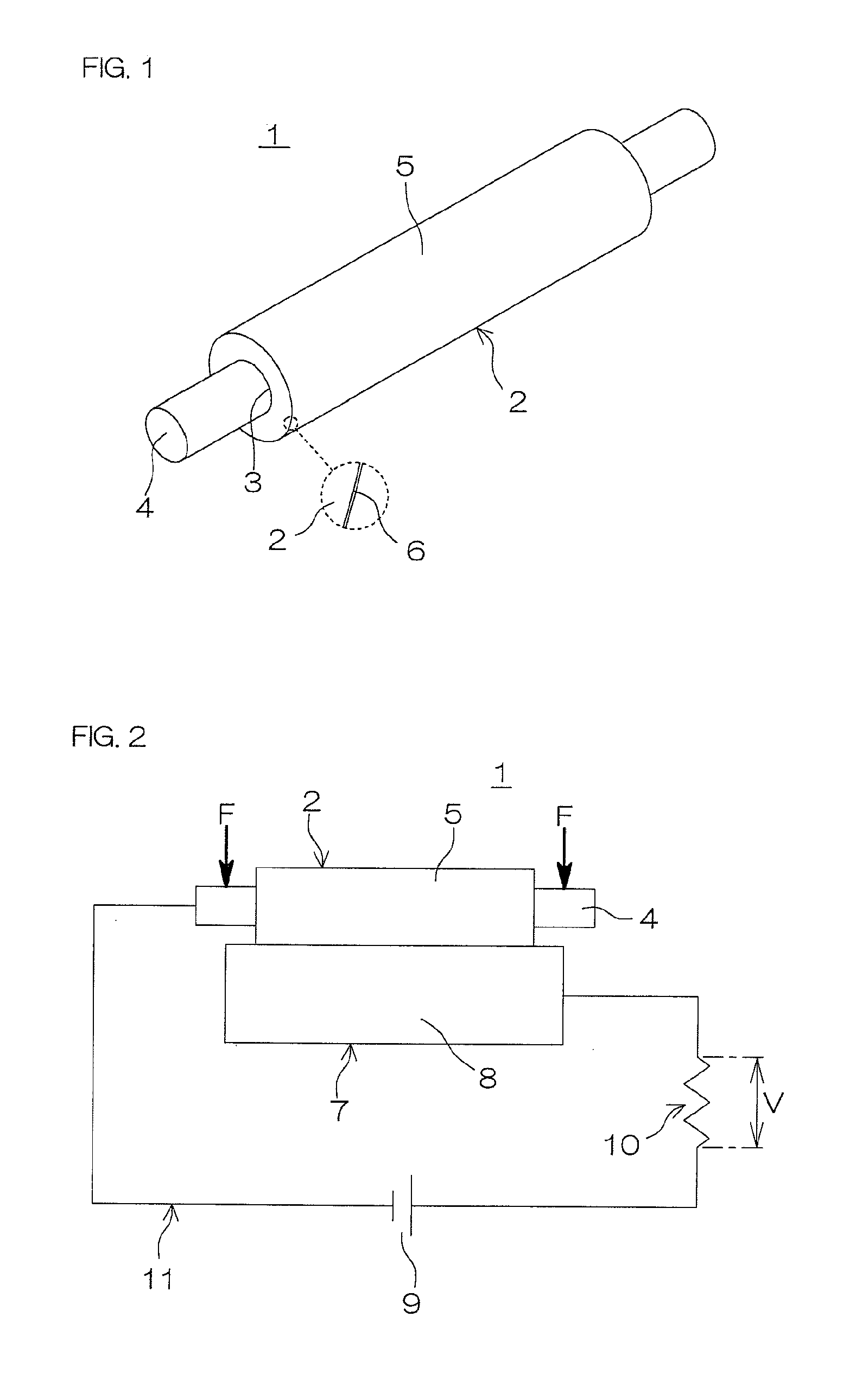
An electrically conductive roller is provided which has a stable roller resistance with little batch-to-batch variation in roller resistance and substantially without influence of environmental conditions and the like, and is unlikely to contaminate the photo receptor. The electrically conductive roller (1) includes a roller body (2) made of a crosslinking product of an electrically conductive rubber composition prepared by blending a potassium salt of an anion having a fluoro group and a sulfonyl group in its molecule and a crosslinking component in a base polymer which is a mixture containing an epichlorohydrin rubber E and a diene rubber N in a mass ratio E / N of 50 / 50 to 80 / 20, and an oxide film (6) formed in an outer peripheral surface (5) thereof by irradiation with ultraviolet radiation.

Description

TECHNICAL FIELD[0001]The present invention relates to an electrically conductive roller which can be advantageously used as a charging roller or the like in an electrophotographic image forming apparatus such as a laser printer, an electrostatic copying machine, a plain paper facsimile machines or a printer-copier-facsimile multifunction machine.BACKGROUND ART[0002]Electrophotographic image forming apparatuses have been improved in various ways in order to satisfy requirements for higher printing speed, higher image quality, full-color image formation and smaller size.[0003]In order to increase the printing speed of such an image forming apparatus, it is effective to minimize the electrical resistance of a charging roller which is adapted to electrically charge a drum-shaped photoreceptor in contact with a surface of the photoreceptor.[0004]A popular electrically conductive roller serving as the charging roller includes a roller body having a surface layer at least including an oute...

Claims


Application Information

Patent Timeline
IPC IPC(8): B05C1/08G03G15/02
CPCG03G15/0233
Inventor TAJIMA, KEI
Owner SUMITOMO RUBBER IND LTD
Learn More