Motion Detecting Device, Method Of Providing The Same, And Method Of Detecting Movement

a technology of motion detection and motion sensor, which is applied in the direction of heating types, instruments, separation processes, etc., can solve the problems of limiting the likelihood of eventual commercial success, cameras or pir sensors deployed on walls, ceilings, or above doors, and adverse aesthetic effects on the area around where cameras or pir sensors are deployed

Active Publication Date: 2013-10-31
GEORGIA TECH RES CORP
View PDF3 Cites 2 Cited by
  • Summary
  • Abstract
  • Description
  • Claims
  • Application Information

AI Technical Summary

Problems solved by technology

Although these solutions are cost-effective on an individual sensor basis, they are not without some important drawbacks that limit the likelihood of eventual commercial success through broad consumer acceptance.
The use of these high fidelity sensors in certain spaces often raises concerns about the balance between value-added services and acceptable surveillance, particularly in home settings.
Generally, cameras or PIR sensors when deployed on walls, on ceilings, or above a door have adverse aesthetics effects on the area around where the cameras or PIR sensors are deployed.
Furthermore, the large number of sensors required for coverage of an entire building presents an inherent complexity hurdle.
Installation and maintenance of (typically) tens of sensors in a home, or hundreds to thousands of sensors in a larger building such as a hotel, hospital, or assisted living facility, results in high costs during installation and operation.
It is often difficult to balance the value of in-home sensing and the complexity of the sensing infrastructure.
The installation of these sensors was difficult, time-consuming, and required direct access to the underside of the floor.
Though the value of the application was proven, the complexity and cost of the sensing limited the number of homes in which the system could be deployed easily.

Method used


Image

  • Motion Detecting Device, Method Of Providing The Same, And Method Of Detecting Movement
  • Motion Detecting Device, Method Of Providing The Same, And Method Of Detecting Movement
  • Motion Detecting Device, Method Of Providing The Same, And Method Of Detecting Movement

Examples


second embodiment

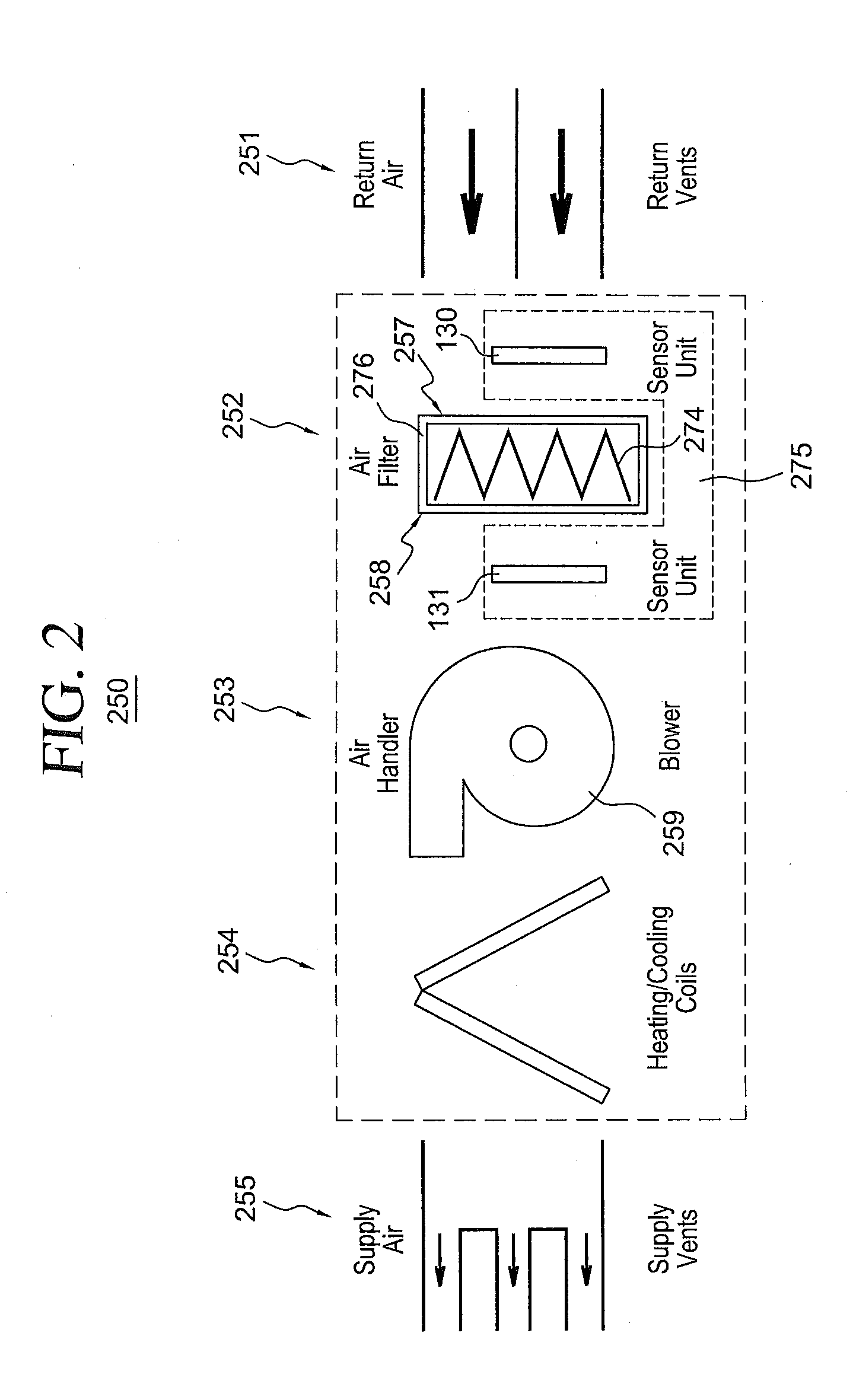
[0074]Turning to another embodiment, FIG. 6 illustrates an implementation of sensing device 610 of a motion detecting device 600 in an exemplary HVAC system 650, according to a Motion detecting device 600 is merely exemplary and is not limited to the embodiments presented herein. Motion detecting device 600 can be employed in many different embodiments or examples not specifically depicted or described herein. For example, motion detecting device 600 can be deployed in HVAC systems in a commercial or residential setting not specifically depicted or described herein.

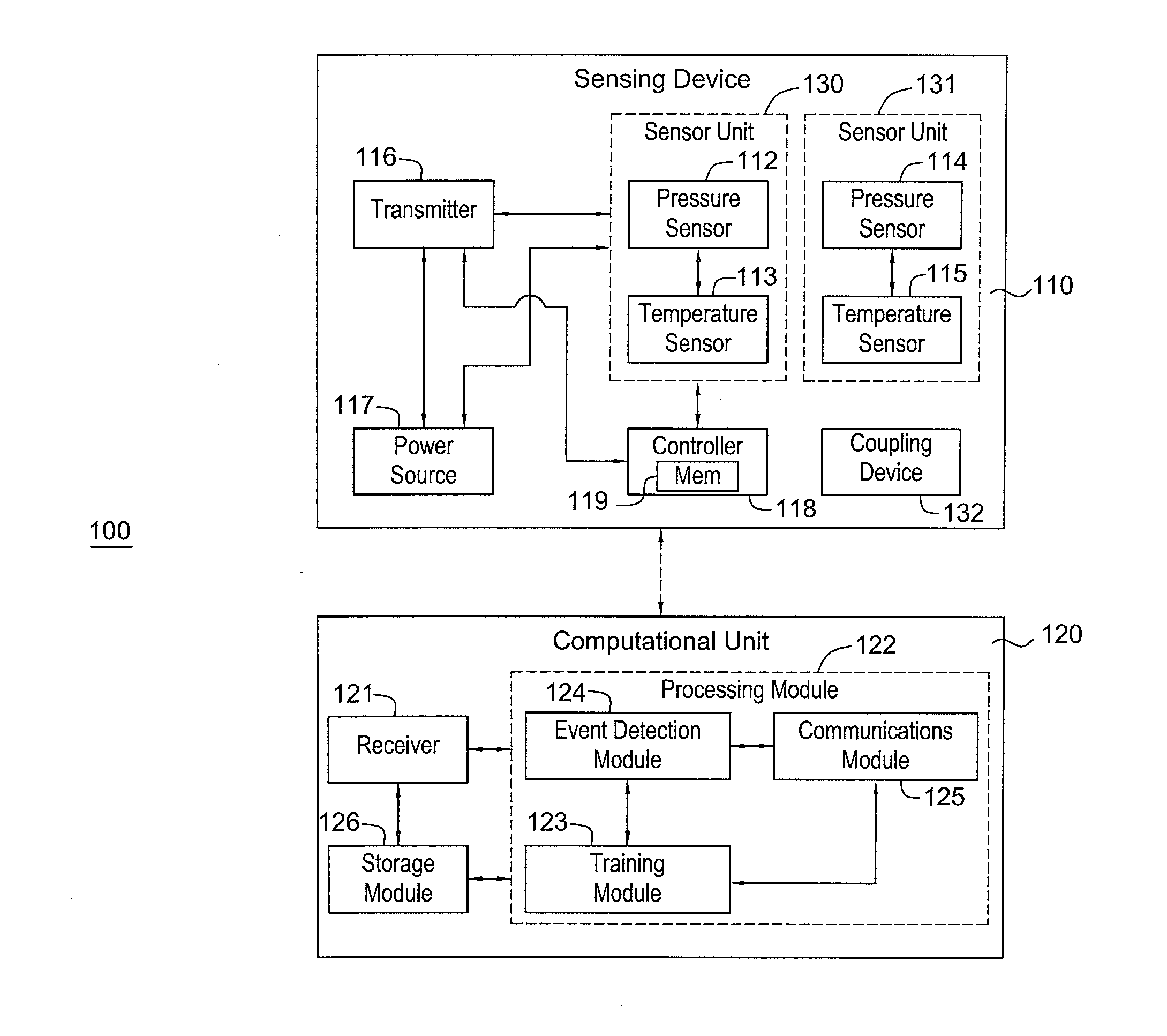
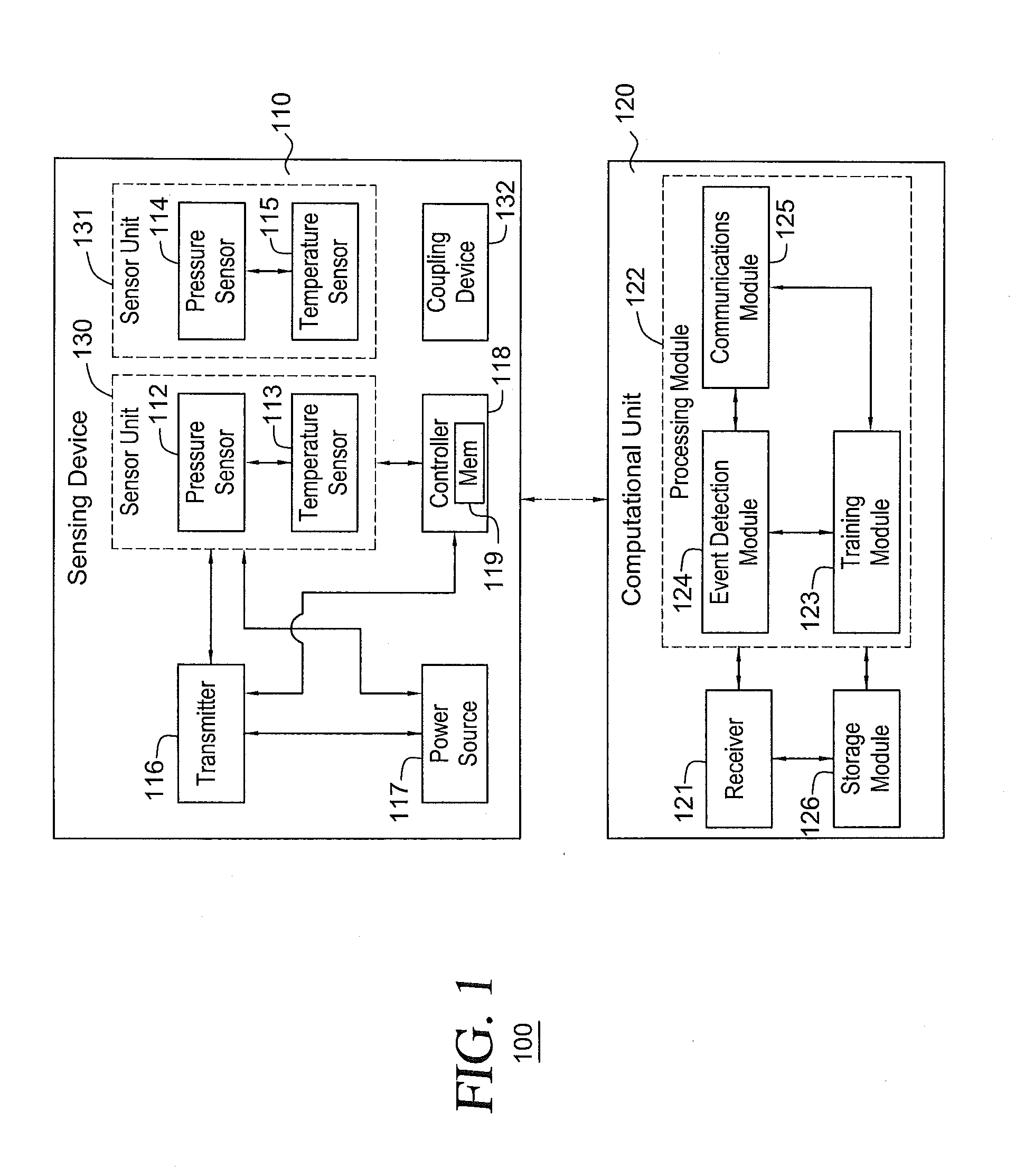
[0075]In this example, motion detecting device 600 can include: (a) sensing device 610; and (b) computational unit 120 (FIG. 1). Sensing device 610 can be part of air filter 653. For example, air filter 653 can include: (a) filter and / or fibrous material 274; (b) an outer frame 676 located around fibrous material 274; (c) at least one sensor unit 130 and 131 coupled to at least one of fibrous material 274 or outer frame ...

third embodiment

[0076]Turning to yet still another embodiment, FIG. 7 illustrates an implementation of sensing device 710 of a motion detecting device 700 in an exemplary HVAC system 750, according to a Motion detecting device 700 is merely exemplary and is not limited to the embodiments presented herein. Motion detecting device 700 can be employed in many different embodiments or examples not specifically depicted or described herein. For example, motion detecting device 700 can be deployed in HVAC systems in a commercial or residential setting not specifically depicted or described herein.

[0077]In this example, motion detecting device 700 can include: (a) sensing device 710; and (b) computational unit 720. Sensing device 710 could be integrally and / or permanently part of a HVAC system. For example, sensing device 710 (or sensor units 130 and / or 131) can be located at or in blower 759. In some embodiments, computational unit 720 can be also located inside HVAC system 750 (e.g., inside large, non-...


PUM

PropertyMeasurementUnit
pressureaaaaaaaaaa
atmospheric pressureaaaaaaaaaa
air pressureaaaaaaaaaa

Abstract

In some embodiments, a motion detecting device is configured to detect whether one or more movement events have occurred. The motion detecting device can include: (a) a processing module configured to run on a computational unit; and (b) a sensing device having: (1) one or more pressure sensors configured to provide two or more pressure measurements; and (2) a transmitter electrically coupled to the one or more pressure sensors and configured to transmit the two or more pressure measurements to the computational unit. The processing module is configured to use the two or more pressure measurements to determine whether the one or more movement events have occurred. The sensing device can be configured to be placed in at least one of ductwork of a heating, ventilation, and air conditioning system or an air handler of the heating, ventilation, and air conditioning system. Other embodiments are disclosed.

Description

CROSS-REFERENCE TO RELATED APPLICATIONS[0001]This application claims is a continuation of U.S. patent application Ser. No. 12 / 778,771, filed May 12, 2010. U.S. patent application Ser. No. 12 / 778,771 claims priority from U.S. Provisional Application No. 61 / 177,482, filed May 12, 2009. U.S. patent application Ser. No. 12 / 778,771 and U.S. Provisional Application No. 61 / 177,482 is incorporated herein by referenceFIELD OF THE INVENTION[0002]This invention relates generally to apparatuses and methods for detecting movement events, and relates more particularly to such apparatuses and methods that detecting movement events using heating, ventilation, and air conditioning (HVAC) systems.DESCRIPTION OF THE BACKGROUND[0003]Development of low-cost and easy-to-deploy sensing systems to support movement detection in a home or another building has been an active research area. Much of the development has centered on the deployment of a network of inexpensive sensors throughout the home, such as m...

Claims


Application Information

Patent Timeline
Patent Type & Authority Applications(United States)
IPC IPC(8): G01L13/00
CPCG01L13/00B01D46/10G08B13/20F24F11/30F24F2110/10F24F2120/10F24F2120/14F24F11/52F24F11/58F24F2120/00F24F11/46F24F11/63
Inventor PATEL, SHWETAK N.REYNOLDS, MATTHEW S.ABOWD, GREGORY D.
Owner GEORGIA TECH RES CORP
Why Eureka
Try Eureka