Fabric pin

a fabric clip and pin technology, applied in the field of fabric clips, can solve the problems of inability to maintain the shape of the clothespin, the parts of the clothespin can fall apart, and the clothespin is often not very durable, so as to achieve the effect of increasing the strength of the spring structure, ensuring the stability of the fabric clip, and ensuring the quality of the fabric clip

Inactive Publication Date: 2013-11-07
EKLIPSE
View PDF0 Cites 4 Cited by
  • Summary
  • Abstract
  • Description
  • Claims
  • Application Information

AI Technical Summary

Benefits of technology

[0015]Preferably, the spring structure has an inner ring segment portion with a first end being connected to a proximal end region of the first leg and a second end being connected to a proximal end region of the second leg. In this context, proximal ends of the legs relate to longitudinal ends being opposed to the distal ends thereof. Such an inner ring segment portion allows for applying additional clamping force on the first and second legs and thereby providing a secondary spring tension. Furthermore, it allows for accommodating the clothesline for storing the fabric pin on the clothesline when no fabric is fixed by the fabric pin. For preventing the inner ring segment portion from unintentionally accommodating a clothesline when clamping a fabric, the fabric pin can have an according blocking structure such as nodes being arranged at the ends of the inner ring segment portion. Thereby, the fabric pin preferably comprises a rib connecting the outer ring segment portion of the spring structure to the inner ring segment portion of the spring structure. Like this, the outer ring segment portion and the inner ring segment portion of the spring structure can be held in a stable position with regard to each other. In particular, the rib can provide for more stability of the fabric clip regarding twisting movements. It also can increase strength of the spring structure and decrease the loss of strength due to changes in temperature in particular if the fabric clip is made of a plastic material.
[0016]Preferably, the first leg has a rounded inner side and the second leg has a rounded inner side wherein the inner side of the first leg and the inner side of the second leg are facing each other. In this context, inner sides of the first and second legs relate to the sides of the legs facing each other and particularly being in contact with the fabric when clamping it. Such rounded inner sides can allow for a gentle insertion of the fabric and the clothesline wherein the legs are smoothly flexed apart. In particular, the inner sides can be rounded such that the legs are closest to each other at about half of their lengths.
[0017]Preferably, the first leg has an outer side provided with a web and being opposed to the inner side of the first leg and the second leg has an outer side provided with a web and being opposed to the inner side of the second leg. Such webs can provide rigidity to the legs in order to minimize deflection of the legs while clamping. In particular, deformation of the legs due to the forces induced by the spring structure can be reduced. Thereby, the web of the outer side of the first leg preferably broadens into the direction of the distal end region of the first leg and the web of the outer side of the second leg preferably broadens into the direction of the distal end region of the second leg. Like this, variable rigidity can be provided to the legs ov...

Problems solved by technology

Thereby, in a manufacturing process such assembling can be a comparably complicated step having an impact on the overall manufacturing efficiency.
Also, particularly when being often used, the parts of such clothespins can fall apart.
Since wood usually is sensitive to ...

Method used


Image

  • Fabric pin
  • Fabric pin
  • Fabric pin

Examples


first embodiment

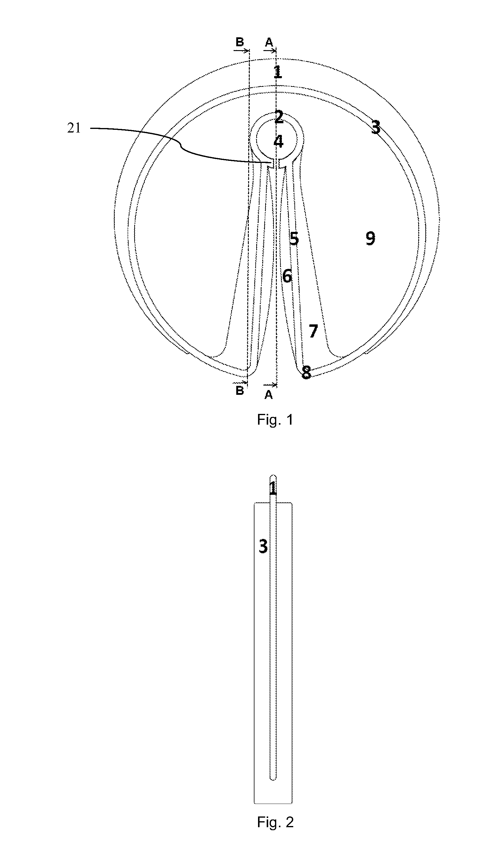
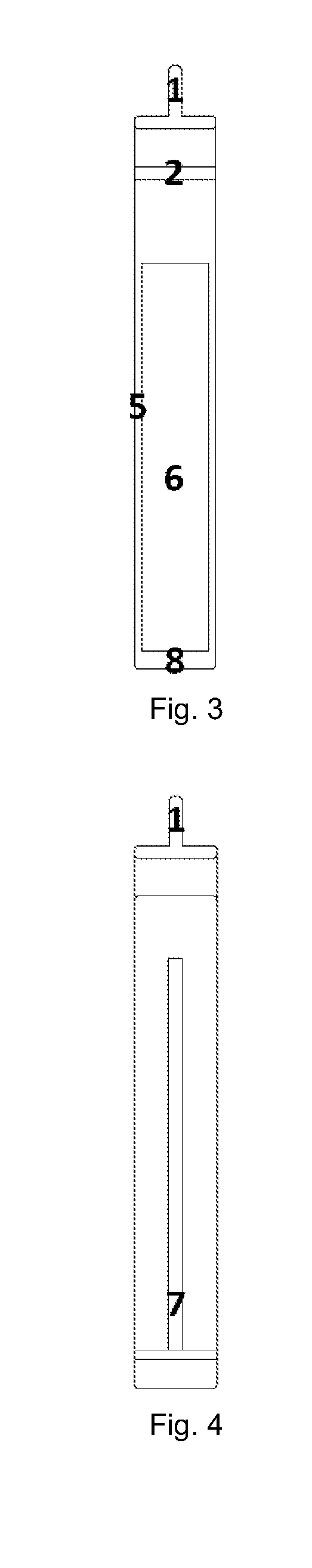
[0035]FIG. 1 shows a clothespin as a fabric pin comprising an elongate first leg, an elongate second leg and a spring structure. Each of the first leg and the second leg has a flange portion 5, a curved contact surface 6 as rounded inner side and a web 7 at its outer side. The first and second legs are arranged side by side wherein their curved contact surfaces 6 are facing each other. The spring structure has an outer ring as outer ring segment portion and an inner flange ring 2 as an inner ring segment portion. Each of the inner flange ring and the outer ring has a first end in a circumferential direction and a second end in an opposite circumferential direction. Near the first end and the second end, the inner flange ring 2 is connected to a proximal end of the first leg and to a proximal end of the second leg, respectively. Each of the first and second ends of the inner flange ring 2 projects from the according connection with the first or second leg, respectively, towards the o...

second embodiment

[0043]FIG. 5, FIG. 6 and FIG. 7 show a clothespin as a fabric pin which generally is of a similar design as the clothespin shown in FIGS. 1 to 4. Thereby, it comprises an elongate first leg, an elongate second leg and a spring structure. Each of the first leg and the second leg has a flange portion 50, a curved contact surface 60 as rounded inner side and a web 70 at its outer side. The first and second legs are arranged side by side wherein their curved contact surfaces 60 are facing each other.

[0044]The spring structure has an outer ring with an outer diameter of about 8.1 centimetres (3.188 inches) as outer ring segment portion and an inner flange ring 20 with an inner diameter of about 1 centimetre (0.375 inches), a thickness of about 0.2 centimetres (0.07 inches) and a width of about 1 centimetres (0.375 inches) as an inner ring segment portion. Each of the inner flange ring 20 and the outer ring has a first end in a circumferential direction and a second end in an opposite cir...

third embodiment

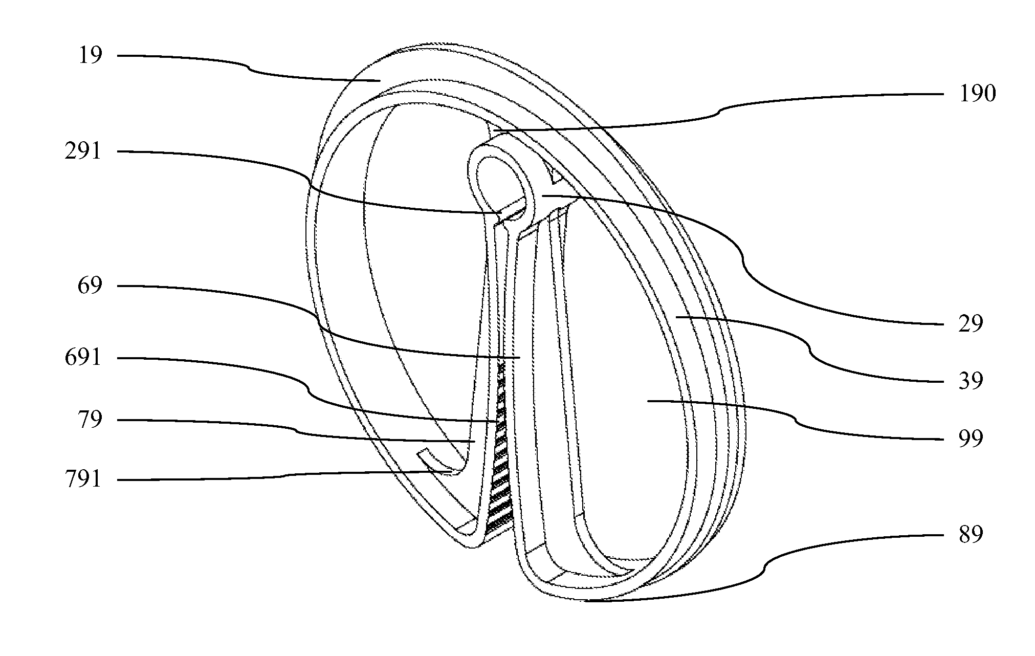
[0049]FIG. 8, FIG. 9, FIG. 10 and FIG. 11 show a clothespin as a fabric pin which generally is of a similar design as the clothespin shown in FIGS. 1 to 4 and the clothespin shown in FIGS. 5 to 7. Thereby, it comprises an elongate first leg, an elongate second leg and a spring structure. Each of the first leg and the second leg has a bent flange portion 69 with a curved contact surface as rounded inner side and a web 79 at its outer side. About one half of the curved contact surface of the flange portion 69 of each of the first and second legs is provided with essentially horizontal teeth 691 as a structure for enhancing friction between the first and second legs and a fabric. The first and second legs are arranged side by side wherein the curved contact surfaces of the bent flange portions 69 are facing each other. The spring structure has an outer ring as outer ring segment portion and an inner flange ring 29 as an inner ring segment portion. Each of the inner flange ring 29 and t...


PUM


Abstract

A fabric pin for fixing a fabric on a clothesline comprises a first leg, a second leg and a spring structure. The spring structure is arranged to force the first leg and the second leg in a clamping position in which the fabric is clampable between the first leg and the second leg. The first leg, the second leg, and the spring structure are integrally formed. The spring structure has an outer ring segment portion with a first end and a second end, wherein the first end of the ring segment portion of the spring structure is connected to a distal end region of the first leg and the second end of the ring segment portion of the spring structure is connected to a distal end region of the second leg. The first leg and the second leg are arranged inside the outer ring segment portion of the spring structure.

Description

CROSS-REFERENCE TO RELATED APPLICATIONS; BENEFIT CLAIM[0001]This application is a U.S. National Stage Application filed under 35 U.S.C. §371 of International Application No. PCT / US11 / 62818 filed Dec. 1, 2011, which claims priority to U.S. Provisional Patent Application No. 61 / 421,987 filed Dec. 10, 2010.FIELD[0002]Embodiments relate to a fabric pin according to the preamble of independent claim 1. Such fabric pins comprising a first leg, a second leg and a spring structure, wherein the spring structure is arranged to force the first leg and the second leg in a clamping position in which the fabric is clampable between the first leg and the second leg and the first leg, the second leg and the spring structure are integrally formed as one piece, can be used for fixing a fabric on a clothesline.BACKGROUND[0003]For drying or airing fabrics such as clothes and the like it is widespread to hang the fabrics on lines or cords in the fresh air or in a laundry room. Such a hanging provides fo...

Claims


Application Information

Patent Timeline
IPC IPC(8): D06F55/02
CPCD06F55/02D06F55/00Y10T24/44769
Inventor EARLEY, III, CHARLES MARION
Owner EKLIPSE
Why Eureka
Try Eureka