Cooling assembly

a technology of cooling assembly and heat exchanger, which is applied in the direction of air heater, lighting and heating apparatus, and semiconductor/solid-state device details, etc., can solve the problems of heat exchanger blockage in known cooling assembly

Active Publication Date: 2013-11-07
ABB (SCHWEIZ) AG
View PDF59 Cites 9 Cited by
  • Summary
  • Abstract
  • Description
  • Claims
  • Application Information

AI Technical Summary

Benefits of technology

[0011]The cooling assembly of the disclosure can help reduce the risk of clogging of heat exchanger units.

Problems solved by technology

Clogging of heat exchanger in known cooling assemblies can occur due to contaminant particles present in cooling air flow.

Method used


Image

  • Cooling assembly
  • Cooling assembly
  • Cooling assembly

Examples


Embodiment Construction

[0009]The present disclosure provides a cooling assembly, which can help alleviate clogging of a heat exchanger due to contaminant particles present in cooling air flow.

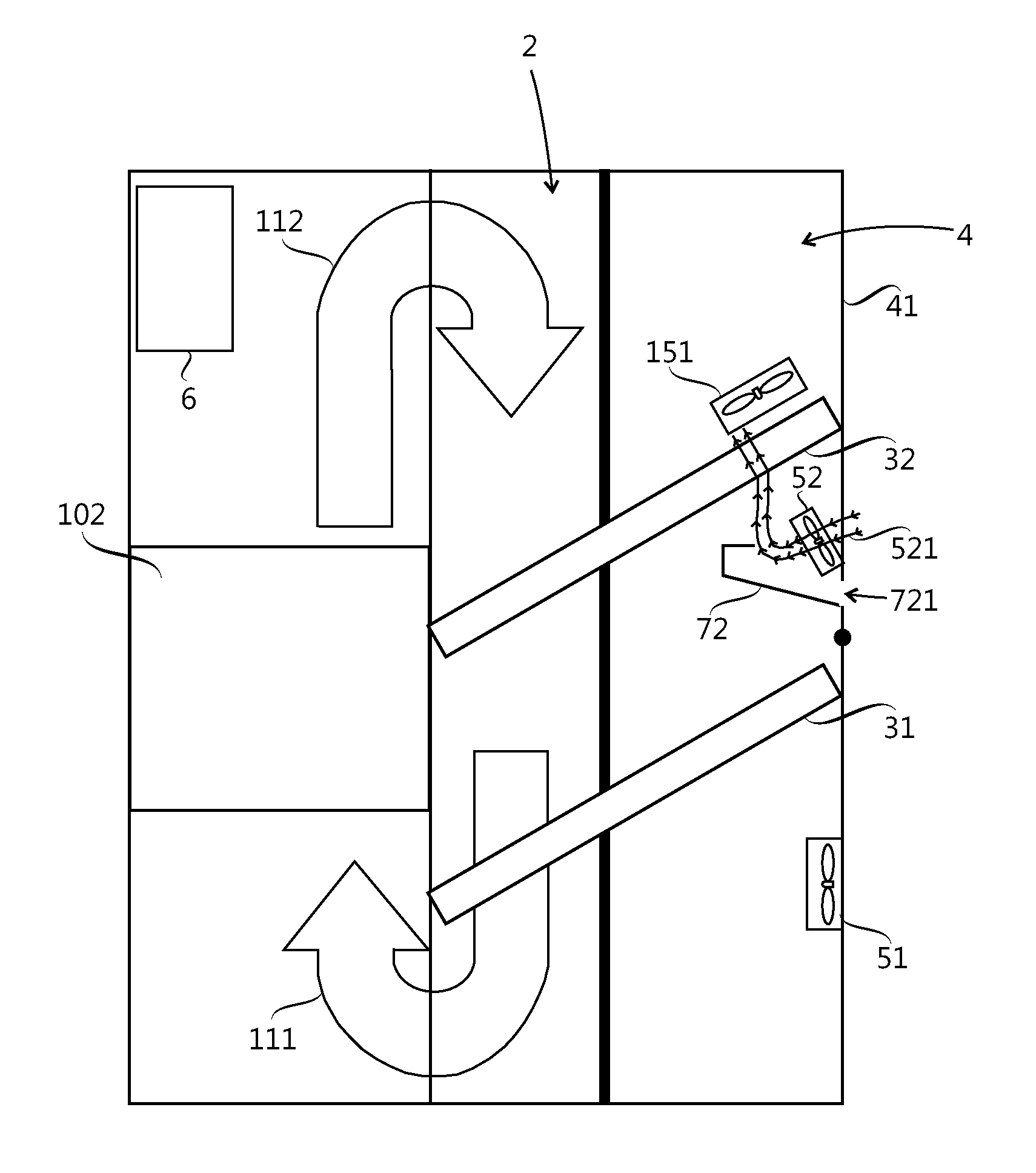
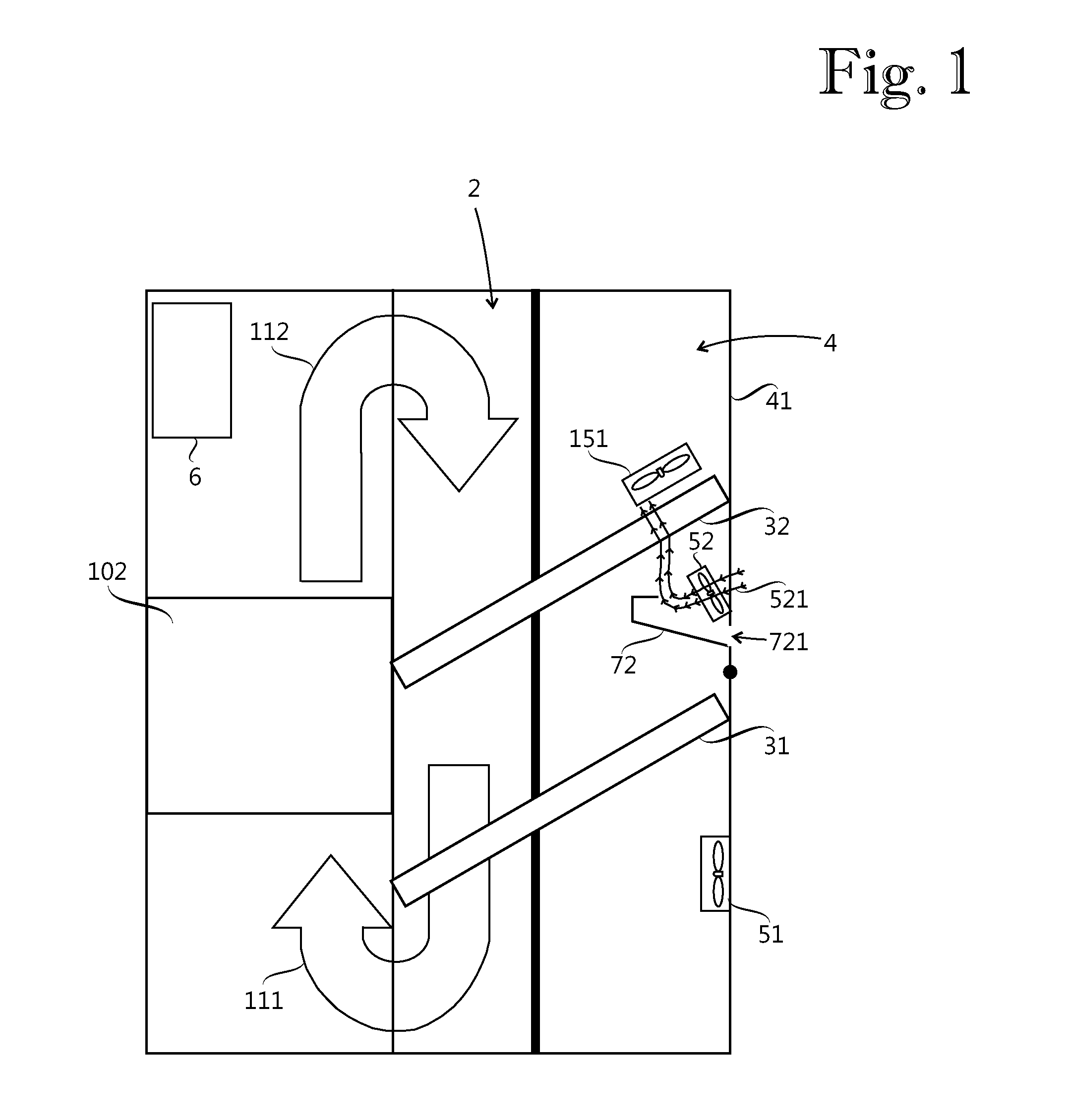
[0010]The disclosure provides a cooling assembly with a first dust tray located in the vertical direction between a first heat exchanger unit and a second heat exchanger unit, the first dust tray being adapted to receive and retain at least part of contaminant particles present in a first cooling air flow generated by a first fan and directed towards the first dust tray.

[0011]The cooling assembly of the disclosure can help reduce the risk of clogging of heat exchanger units.

[0012]FIG. 1 is shows an exemplary cooling assembly having a device chamber 2, a cooling chamber 4, a heat exchanger serving as an exemplary heat exchanger means, a fan serving as a fan means for cooling, a first dust tray 72 and control means 6 (e.g., specifically programmed processor) for controlling the fan means. FIG. 1 shows the cooling assem...


PUM


Abstract

A cooling assembly is disclosed having a device chamber, a cooling chamber, a heat exchanger, a fan and a controller, the heat exchanger having a first heat exchanger unit and a second heat exchanger unit located above the first heat exchanger unit. The fan includes a first fan adapted to generate a first cooling air flow. The cooling assembly further includes a first dust tray located between the first heat exchanger unit and the second heat exchanger unit, the first cooling air flow being directed towards the first dust tray, the first dust tray being adapted to receive and retain at least part of contaminant particles present in the first cooling air flow, the device chamber being separated from the cooling chamber.

Description

RELATED APPLICATION(S)[0001]This application claims priority under 35 U.S.C. §119 to European Patent Application No. 12166363.7 filed in Europe on May 2, 2012, the entire contents of which are hereby incorporated by reference in its entirety.FIELD[0002]The present disclosure relates to a cooling assembly.BACKGROUND INFORMATION[0003]Clogging of heat exchanger in known cooling assemblies can occur due to contaminant particles present in cooling air flow.SUMMARY[0004]A cooling assembly is disclosed, comprising: a device chamber; a cooling chamber; heat exchanger means, wherein the heat exchanger means includes a first heat exchanger unit and a second heat exchanger unit located above the first heat exchanger unit, each of the first and second heat exchanger units including a first end located in the device chamber, and a second end located in the cooling chamber, the heat exchanger means being adapted to transfer heat from the device chamber to the cooling chamber; fan means, the fan m...

Claims


Application Information

Patent Timeline
Patent Type & Authority Applications(United States)
IPC IPC(8): F28G1/16
CPCH05K7/20181F28G1/166H05K7/202F28G1/16
Inventor KOIVULUOMA, TIMOAGOSTINI, BRUNOHABERT, MATHIEUSIIRILA, JOUKO
Owner ABB (SCHWEIZ) AG
Why Eureka
Try Eureka