Sweep-flow methods and clogging disrupters, for expanded bed chromatography of liquids with suspended particulates

a technology of suspended particulates and disrupters, which is applied in the field of biochemistry and purification, can solve the problems of clogging, heavy load of particulates, and valuable target molecules to be released by beads, and achieves the effects of simple, cost-effective, and prevent or reduce the formation and growth

Inactive Publication Date: 2007-08-30
ALASKA ANDREW
View PDF0 Cites 14 Cited by
  • Summary
  • Abstract
  • Description
  • Claims
  • Application Information

AI Technical Summary

Benefits of technology

[0057] Another object of this invention is to disclose a simple, cost-effective device for use in expanded bed chromatography or other affinity binding purification, to prevent or reduce the formation and growth of cakes or clogging on the inlet device(s) that support the sorbent material in a column.
[0058] Another object of this invention is to disclose a simple, cost-effective device and method for use in expanded bed chromatography or other affinity purification, which can optimize the flow system in ways that can stabilize and protect the column during all processing steps, and that can sharpen the peak and reduce the volume of eluant that contains the targeted product.
[0059] Another object of this invention is to disclose a device and method for use in expanded bed chromatography or other affinity purification, which can eliminate the need for a piston, rotating distributor, or other device that requires moving parts to be placed inside a column where the moving parts would have to interact with potentially abrasive sorbent materials.
[0060] Devices and methods are disclosed herein for expanded bed adsorption and / or chromatography, which can: (i) reduce or in some cases eliminate the need for pistons, rotating distributor arms, or other moving parts that will directly contact sorbent material in a column; (ii) reduce the risk of clogging, fouling, and cake formation on an inlet flow-distributor plate and / or inlet screen that supports the sorbent material; and, (iii) allow efficient elution of a packed (rather than fluidized) bed. This system can handle a wider range of liquids, having heavier particulate loads, than can be handled today using expanded bed chromatography.
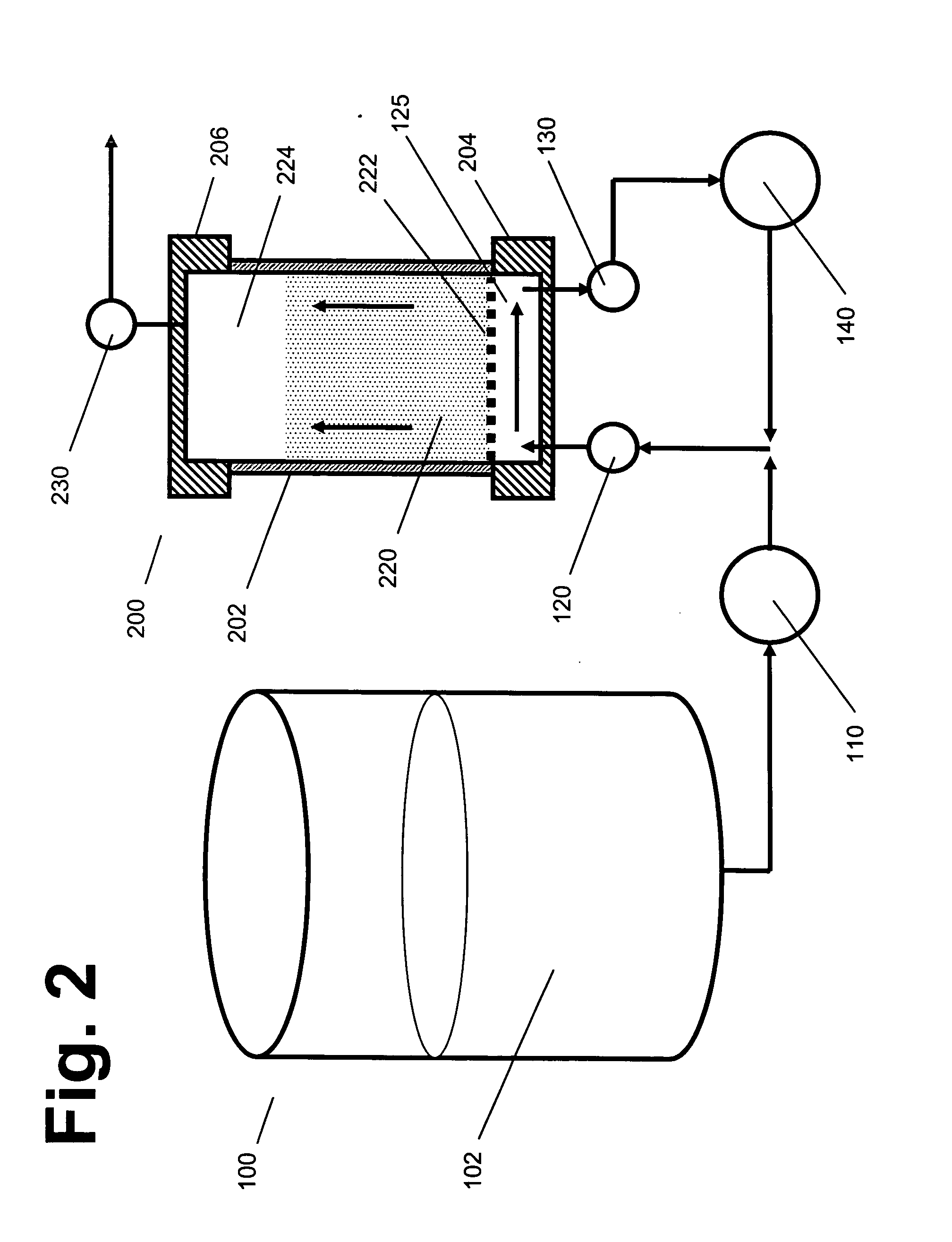
[0061] One enhancement provides both an inlet port and an outlet port, positioned near the bottom of the column, beneath any distributor plate and / or inlet screen or mesh that the sorbent material rests upon. The use of both an inlet port and an outlet port, in the bottom region of a column, can establish a horizontal form of tangential or “sweeping” flow that will sweep across the lower surface of a distributor plate of inlet screen, reducing the risks and rates of formation of particulate cakes and the problems that arise from such cakes. This tangent-flow (or sweep-flow) system has been tested in prototype columns, and it is surprisingly effective in preventing and suppressing clogging and cake formation, even when used to process liquids that contain heavy loads of particulates.
[0062] Another enhancement involves the use of pulsatile flow, and / or a vibrating or intermittent hammering or knocking mechanism that can disrupt and reduce the formation of cakes, lumps, or other aggregates. When used in combination with a sweep-flow system, these enhancements can substantially extend the range of liquids that can be purified in a practical and efficient manner, using a screen or mesh to enable elution of a true packed bed, after loading and washing have been completed. Packed bed elution is more efficient than fluidized bed elution, and can provide product outputs that are more concentrated and purified.

Problems solved by technology

One of the main problems addressed by expanded bed chromatography is that many liquids that contain valuable target molecules also contain heavy loads of particulates.
Such particulates can clog up the screens that are used to hold beads, resins, or other sorbent materials in a column while liquids pass through the column; they can also cause other problems, such as forming clumps inside a column.
However, this washing step will not cause the valuable target molecules to be released by the beads.
Despite the advances that have been made in expanded bed chromatography over the past 10 years, several important problems still remain, and those problems limit or impede (and in some cases prohibit) the processing and purification of various liquids and molecules, using true expanded bed methods and equipment.
The formation of a cake, on an inlet screen or flow-distributor plate, will then block and impede the desired flow patterns during the rest of the processing.
Within the channels, flow velocities are too high, and in non-channel regions, flow velocities are too low.
These uneven flow rates lead to stagnant zones, uneven processing, and impaired purification.
This can causing even more particulates to accumulate on the screen, in a “vicious circle” type of cascading effect.
This can lead to rapid increases in back-pressure, and it often renders a column unusable from that point on, requiring the process to be shut down so that the mesh can be cleaned.
This will cause the cake to suddenly begin releasing large quantities of cell debris and other contaminants, into the product pool.
This is highly adverse, and it can seriously reduce the utility of the process.
Sorbent beads that are trapped within the interior of those types of aggregates cannot participate fully in binding or elution reactions.
If this happens, the binding capacity of the column is reduced, and purification is impaired.
In addition, it should be recognized that on a practical level, elution and collection of valuable target molecules, using upward flow of an elution liquid, is difficult and problematic, even though it may be desirable in some cases.
Although it theoretically may be possible to carry out “plug flow” elution through a packed bed using upward elution flow, in actual practice, it is common for upward flow of the elution liquid to break apart the packing of the bed, causing the packed bed to become fully or partly fluidized.
This leads to increased costs during any subsequent storage, processing, and purification.
The use of a piston at the top of a column does nothing to prevent or reduce the formation of a particulate cake, on the bottom distributor plate and / or inlet screen.
As a result, all of the cake-related problems mentioned above will continue to apply.
The “sliding piston” design is somewhat complex and expensive, and is subject to a risk of jamming, breakage, or other mechanical problems (especially since “dirty” liquids are usually being processed), as compared to fixed-end column designs.
However, acrylic tubes are not well-suited for intermittent sliding of a piston in the presence of sorbent beads (which can be very abrasive, especially if made from minerals such as zirconia, for greater density).
Stainless steel is more capable of withstanding abrasion, but it is not transparent, so precise lowering of a piston onto a sorbent bed, at the start of an elution stage, becomes difficult, especially when it is difficult to predict the exact level where the bed will settle and compact itself to, at the end of an elution step, after the beads have become partially loaded with target molecules and with debris.
The exit screen, on the lower surface of the piston, frequently becomes somewhat clogged during the loading step.
However, without the mesh, the piston cannot be lowered directly onto the sorbent bed, since the mesh also serves as a baffle and distributor, during elution.
Even and uniform distribution of the elution liquid, across the upper width of the column, can be seriously compromised if the exit screen is removed.
However, those approaches require additional operating delays, expenses, and other burdens, and are not entirely satisfactory.
In addition, those systems still suffer from other problems and limitations, as described above.
It should be recognized that, while expanded bed processing is quite useful for many liquids that do not contain high particulate loads (or that contain no particulate load at all), it is not practical and effective for processing other types of liquids that contain high particulate loads.
As a result, true “expanded bed” processing simply cannot be used for processing many of the types of liquids that could benefit most from such processing.
Briefly, this type of rotating distributor design uses a fluidized bed during all stages of loading, washing, and eluting; therefore, it does not enable true “expanded bed” processing of the type that uses loading and washing of a fluidized bed, followed by elution of a packed bed.
However, this type of column can be operated only in an upward flow mode, and the sorbent bed remains fluidized, during elution.
The presence of internal moving parts that must interact with abrasive sorbent particles within the column results in a fast wear of various components, greater problems with leakage, etc.
It is difficult to disassemble the column for cleaning and sanitation.
The requirement of fluidized bed conditions during elution renders this system unable to achieve the levels of concentration and purity that can be achieved by elution of packed beds.
As a result, the product is more diluted, and the diluted output requires greater downstream processing and expenses.
This design also tends to require heavier and more dense material for the beads, which can increase their expense and make certain types of otherwise desirable substrate materials unavailable for use in this type of column.
However, those designs suffered from other problems and performance shortcomings, and they are not being actively sold by either of the major vendors in this field.

Method used


Image

  • Sweep-flow methods and clogging disrupters, for expanded bed chromatography of liquids with suspended particulates
  • Sweep-flow methods and clogging disrupters, for expanded bed chromatography of liquids with suspended particulates
  • Sweep-flow methods and clogging disrupters, for expanded bed chromatography of liquids with suspended particulates

Examples


Embodiment Construction

[0066] A tangential or “sweep” flow system as summarized above is illustrated in FIG. 2, which provides a cutaway view of a chromatography column 200. Column 200 is being used to process a liquid 102, which is held in tank or vessel 100. Liquid 102 contains both a suspension of particulates (such as cells or cell debris), as well as some concentration of a valuable “target molecule” that is to be purified. With the aid of pump 110, liquid 102 is pumped through an inlet port 120, into a fluid flow compartment 125 positioned at the bottom of column 200.

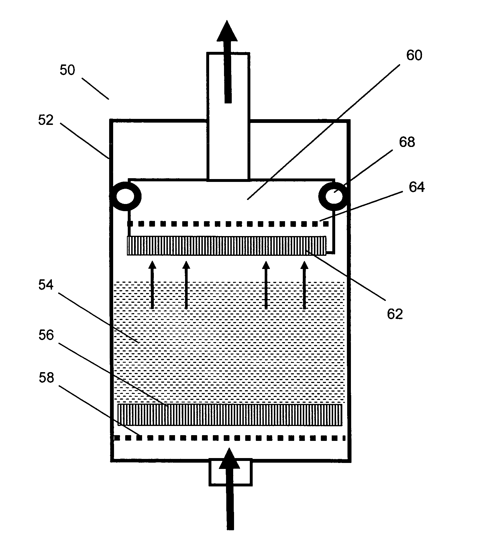
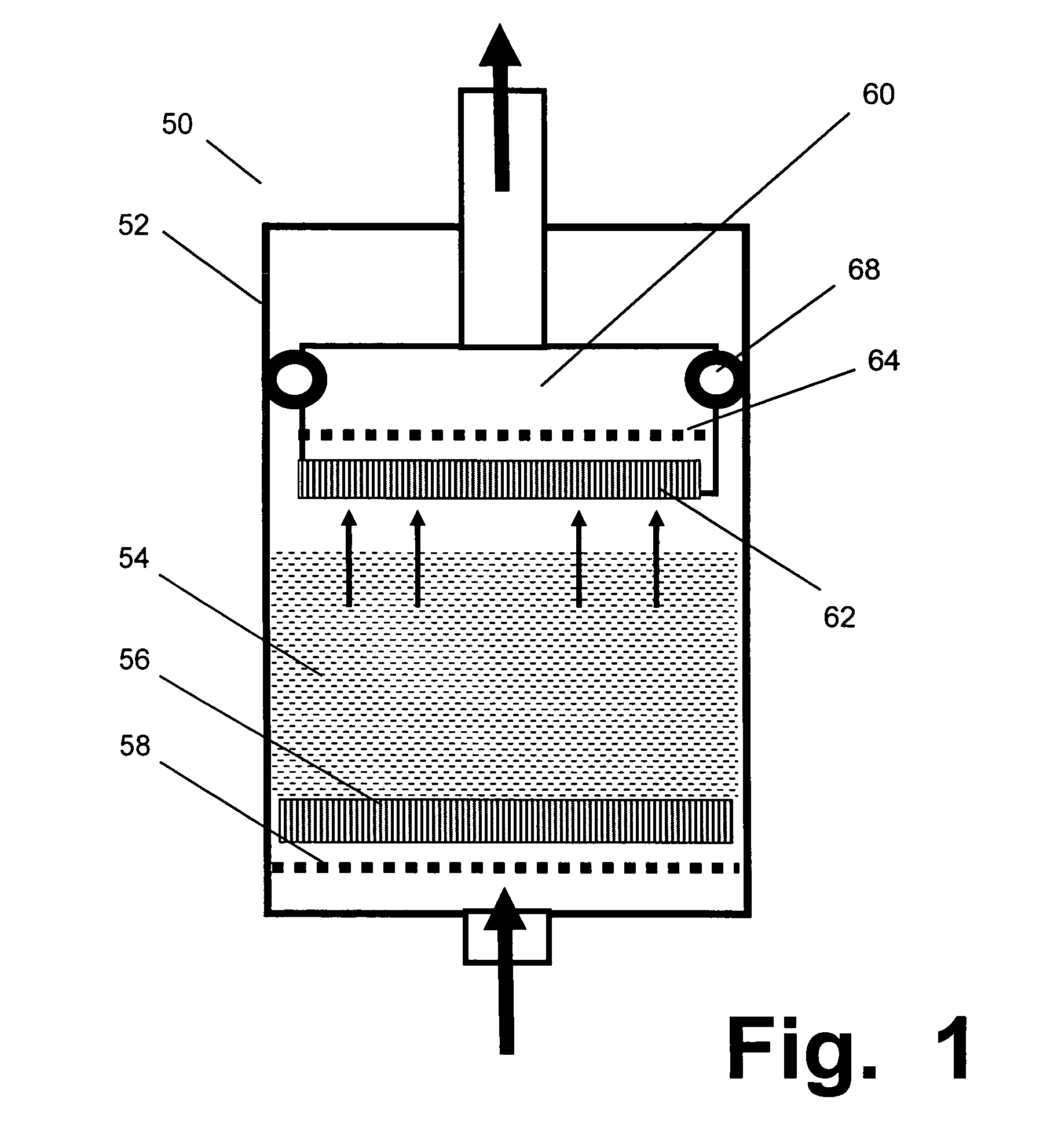
[0067] Column 202 has at least one impermeable wall 202, a lower cap 204, an upper cap 206, and an upper outlet port 230. It can also be provided with a movable piston near the top (such as shown by piston 60, in FIG. 1) and / or any other accessory, appurtenance, or enhancement that is already known or hereafter discovered or developed.

[0068] Inlet port 120 preferably should be provided with a shut-off valve, for convenience. If pump 1...


PUM


Abstract

Devices for expanded bed chromatography use inlet and outlet ports beneath a mesh that supports sorbent beads in a column. Placement of both ports beneath the mesh provides a horizontal “sweep flow” tangential to the mesh, to suppress the formation of particulate cakes on the lower surface of the mesh when liquids containing high particulate loads (such as cells or cell debris) are being processed. This design can be used with vibrators, hammering devices, intermittent reverse flow, or other means for disrupting the formation of particulate cakes or aggregates. Disrupters can also be used during elution, to accelerate the release of the valuable molecules from the sorbent. Initial tests indicate that these systems can efficiently handle heavily loaded liquids that would rapidly clog other systems previously known in the art.

Description

RELATED APPLICATION [0001] The Applicant claims the benefit under 35 USC 119(e) of provisional application 60 / 558,259, filed on Mar. 31, 2004.FIELD OF THE INVENTION [0002] This invention relates to biochemistry and purification, and to methods and devices for “expanded bed” chromatography of liquids that contain particulates such as cells or cell debris. BACKGROUND OF THE INVENTION [0003] As used herein, “chromatography” refers to any purification process in which a liquid solution containing one or more types of valuable molecules is passed through a device, referred to herein as a column, that contains a controlled and selected type of reagent or other material (referred to herein as a “sorbent” material) that can be used to purify or at least concentrate the desired and valuable molecules (for convenience, the molecules being purified are referred to herein as “target” molecules). [0004] As an example that is illustrative rather than limiting, the target molecules that need to be...

Claims


Application Information

Patent Timeline
Patent Type & Authority Applications(United States)
IPC IPC(8): B01D15/08
CPCB01D15/1807B01D15/22B01D15/424G01N2030/388G01N30/6017G01N30/603G01N30/38
Inventor ALASKA, ANDREW
Owner ALASKA ANDREW
Why Eureka
Try Eureka