
Implant deployment device

a deployment device and implant technology, applied in the field of implant deployment devices, can solve the problems of incorrect placement of implants, incorrect rotation of distal ends of deployment devices, and implant twisting,

Active Publication Date: 2009-04-02
COOK MEDICAL TECH LLC
View PDF7 Cites 14 Cited by
  • Summary
  • Abstract
  • Description
  • Claims
  • Application Information

AI Technical Summary

Benefits of technology

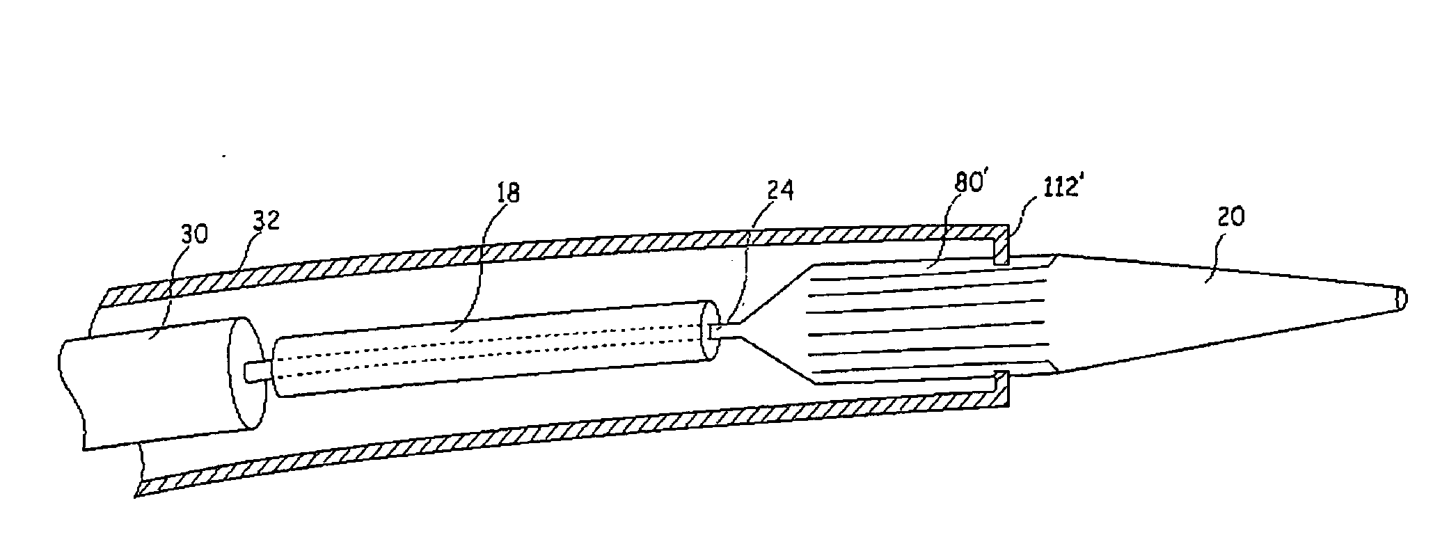
[0009]According to a first aspect of the present invention, there is provided an implant deployment device including: an implant support element onto which an implant may be mounted prior to deployment; a sheath assembly including a sheath operable to cover an implant carried on said implant support element until deployment, said sheath being retractable relative to said implant support element, wherein said sheath has an inner surface and said implant support element has an outer surface, wherein said inner surface of said sheath faces said outer surface of said implant support element; said inner and outer surfaces being generally round in transverse cross-section; and at least one co-operating guide and guide follower being provided on said sheath assembly and implant support element for preventing relative rotation of said sheath and implant support element as said sheath is retracted.
[0010]This implant deployment device allows a sheath to be retracted from an implant that may be mounted on the implant support element without relative rotation between the sheath and the implant support element. The generally round transverse cross-section allows the size of the component parts to be minimized, ensures that flexibility of the device is even in different radial directions, reduces the risk of jamming between the component parts and reduces the risk of kinking.
[0013]In an embodiment, the channel is provided in the outer surface of the implant support element and the projection is provided on an inner surface of the sheath assembly. These may be preferred as they are simple to fabricate.
[0014]The channel may have a depth in the range of 10 to 20% of the diameter of the implant support element. This provides an appropriate size of groove without affecting the properties of the implant support element.
[0015]Preferably the channel and the projection have substantially the same shape in transverse cross-section. The more similarly matched the indentation and projection are, the less rotation is possible.
[0019]According to a second aspect of the present invention, there is provided an implant deployment device including: an implant support element onto which an implant may be mounted prior to deployment; a sheath assembly including a sheath operable to cover an implant carried on said implant support element until deployment, said sheath being retractable relative to said implant support element, wherein said sheath has an inner surface and said implant support element has an outer surface, wherein said inner surface of said sheath faces said outer surface of said implant support element; said inner and outer surfaces being generally round in transverse cross-section, wherein said generally round transverse cross-section is 80 to 90 percent circular; and at least one co-operating channel and projection being provided on said sheath assembly and implant support element, said channel and said projection having substantially a same shape in transverse cross-section, for preventing relative rotation of said sheath and implant support element as said sheath is retracted.

Problems solved by technology

A problem can occur when using prior art implant deployment devices, and, in particular, when it is necessary to twist the implant deployment device in order to rotate the distal end of the implant deployment device to ensure correct orientation of that end of the device, and, in the case of deployment of a prosthesis or implant, correct orientation of the implant in the patient.
With prior art devices, when the surgeon attempts to rotate the proximal end of the deployment device, once the inner catheter has been unlocked from the sheath, that is, when the surgeon rotates the end external to the patient, relative rotation between the pusher member and the sheath and therefore incorrect rotation of the distal end of the deployment device can occur.
This can result in incorrect placement of an implant and in some cases can also lead to twisting of the implant because of the torque generated between the sheath and the pusher member at the distal end of the device.
With this device it would not be possible to manipulate the implant support element in the axial direction (for example, to move a pusher member distally) whilst the locking device is locked.
Whilst this arrangement prevents relative rotation between the handles, the solution is unsatisfactory for several reasons.
A non-round cross-section has increased likelihood of jamming of the telescopic components.
Furthermore, they suffer from uneven flexibility in different radial directions, and increased risk of kinking.
It is also difficult to make such devices sufficiently small for many medical applications.

Method used


Image

  • Implant deployment device
  • Implant deployment device
  • Implant deployment device

Examples


Embodiment Construction

[0029]It is to be understood that the Figures are schematic and do not show the various components in their actual scale. In many instances, the Figures show scaled up components to assist the reader.

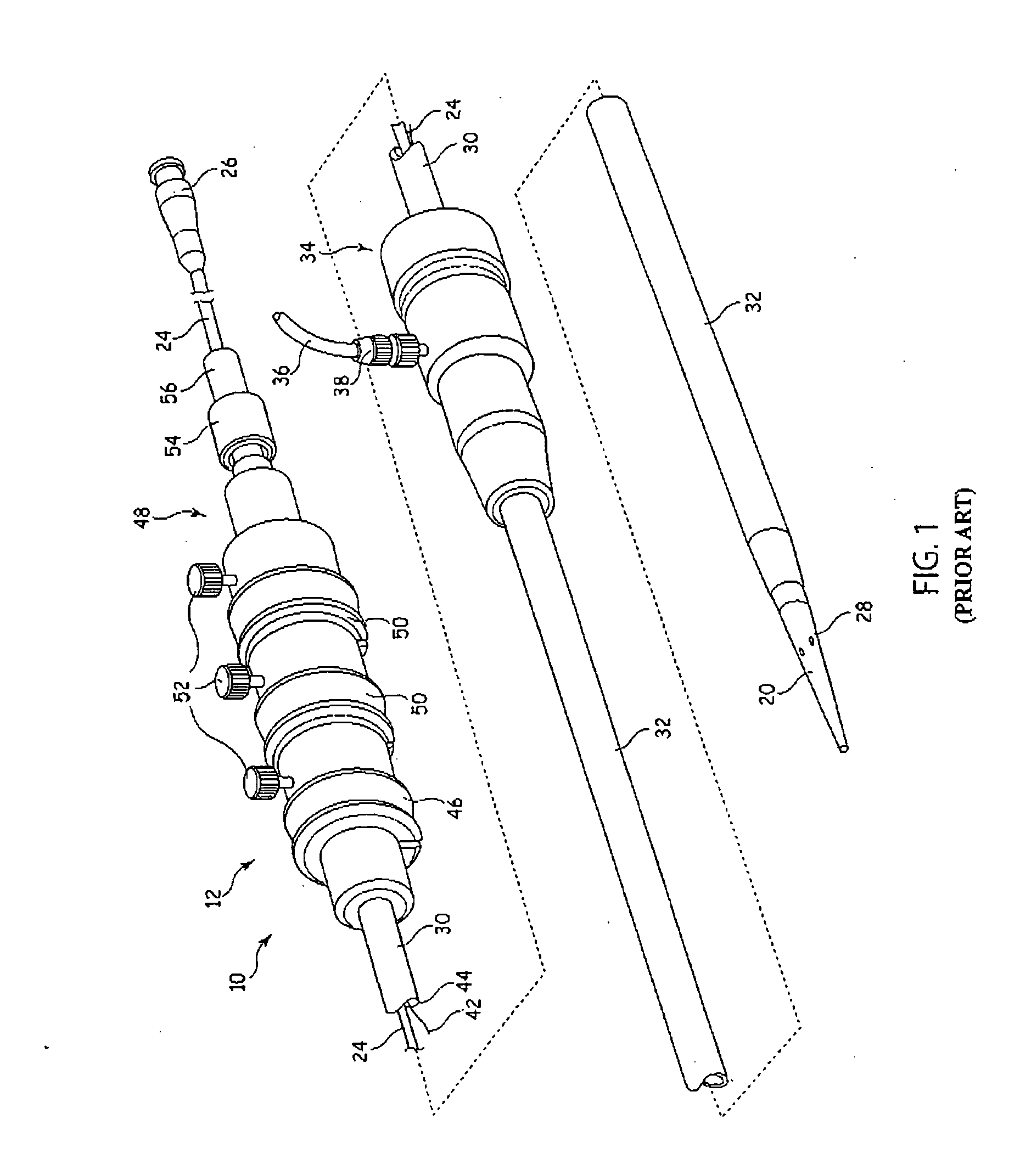
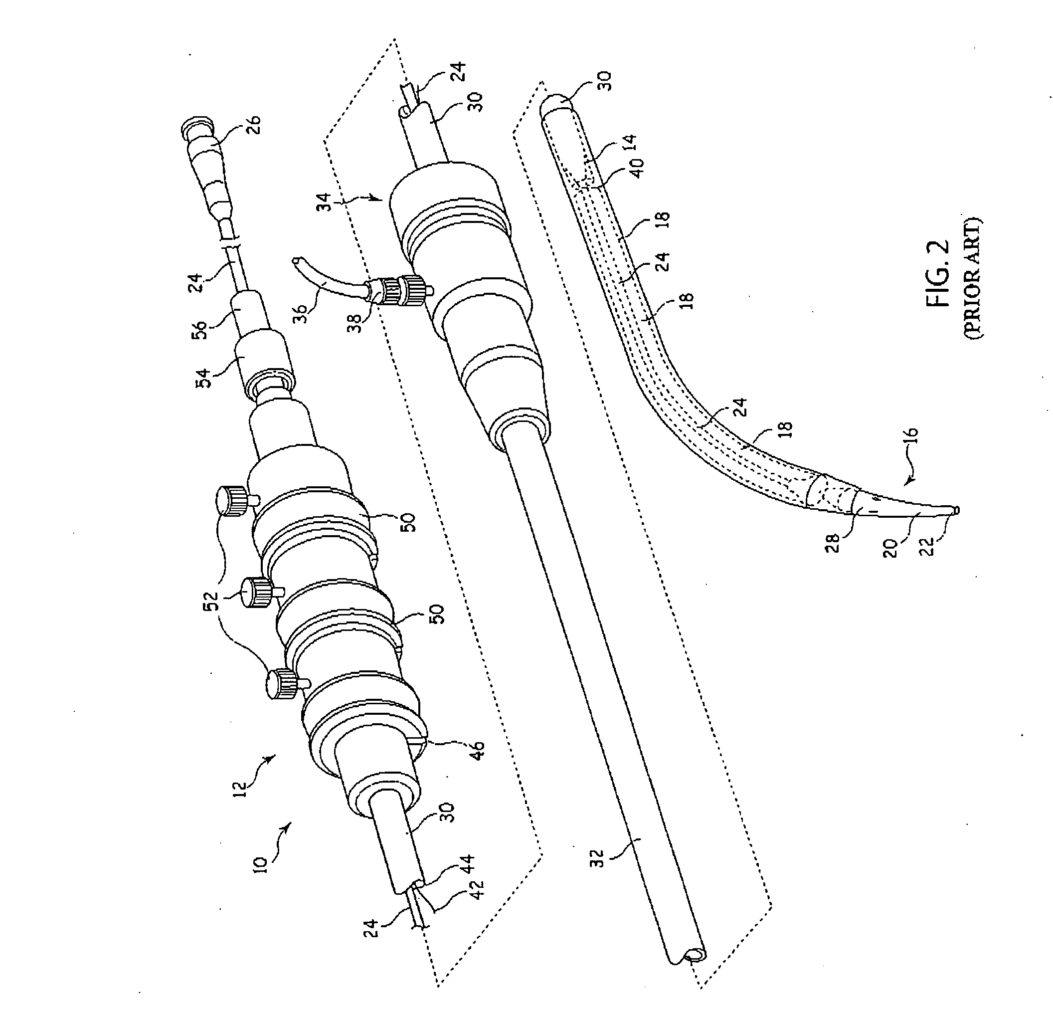
[0030]In this description, when referring to a deployment assembly, the term distal is used to refer to an end of a component which in use is furthest from the surgeon during the medical procedure, including within a patient. The term proximal is used to refer to an end of a component closest to the surgeon and in practise in or adjacent an external manipulation part of the deployment or treatment apparatus.

[0031]On the other hand, when referring to an implant such as a stent or stent graft, the term proximal refers to a location which in use is closest to the patient's heart, in the case of a vascular implant, and the term distal refers to a location furthest from the patient's heart.

[0032]Referring to FIGS. 1 and 2, an implant deployment device 10 includes an external manipulation sec...


PUM


Abstract

An implant deployment device (10) includes a pusher member (30), inner catheter (24), dilator tip (20) upon which an implant (18) is supported during deployment into a lumen of a patient. A sheath (32) substantially surrounds the pusher member (30), the inner catheter (24), the dilator tip (20), covering the implant (18) and containing the implant (18) therewithin. The pusher member (30), inner catheter (24), dilator tip (20) has at least one longitudinal groove formed in its outer surface. This engages with at least one tooth (112) formed in an inner surface of the sheath (32) or an inner surface of a component of the device that is attached to the sheath (32), such as a clamping collar (90) or a locking unit (100). The tooth (112) engages with a longitudinal groove (80) and is able to move along the groove (80) in a longitudinal direction. The engagement of the tooth (112) within the groove (80), however, prevents relative rotation between the sheath (32) and the pusher member (30), inner catheter (24), dilator tip (20). Twisting of an implant (18) supported on the inner catheter (24) is thus avoided.

Description

CROSS-REFERENCE TO RELATED APPLICATIONS[0001]This application claims priority of provisional application Ser. No. 60 / 994,401, filed Sep. 19, 2007.TECHNICAL FIELD[0002]The present invention relates to an implant deployment device. In particular, the implant deployment device is designed to prevent or limit relative rotation between an implant support element and a surrounding sheath.BACKGROUND OF THE INVENTION[0003]Implant deployment devices for introducing intraluminally a stent, stent graft or other implant or prosthesis are typically provided with an outer sheath within which there is provided an implant support element or deployment mechanism such as an inner catheter or cannula which may include a pusher rod and dilator. The sheath has the function of containing various components of the implant deployment device, and in particular the implant, therewithin during the intraluminal introduction procedure. This flexes and twists as it passes through the various lumens of the patien...

Claims


Application Information

Patent Timeline
Patent Type & Authority Applications(United States)
IPC IPC(8): A61F2/84A61B17/00
CPCA61B17/3468A61F2/962A61F2/95
Inventor NIMGAARD, LARS S.
Owner COOK MEDICAL TECH LLC
Learn More