Current Balance Circuit and Multiphase DC-DC Converter and Current Balance Method Thereof

a current balance circuit and converter technology, applied in the direction of electric variable regulation, process and machine control, instruments, etc., can solve the problems of inability to dissipate heat, channel burnt, imbalanced current of each channel, etc., to prevent loop gain of current balance techniqu

Active Publication Date: 2013-11-07
ANPEC ELECTRONICS CORPORATION
View PDF5 Cites 36 Cited by
  • Summary
  • Abstract
  • Description
  • Claims
  • Application Information

AI Technical Summary

Benefits of technology

[0009]It is therefore an objective of the present invention to provide a current balance circuit and a multiphase DC-DC converter and a current balance method thereof capable of shifting a time of starting to increase a voltage of a ramp signal to perform current balance, so as to maintain a slope and amplitude of the ramp signal to be constant to prevent a loop gain of the current balance technique from varying with output and input voltages.

Problems solved by technology

However, since there may be mismatches between the power transistor, inductor, and controller in each channel and on the printed circuit board (PCB), such that the currents of each channel may be imbalance and unequal.
In addition to efficiency reduction, when the imbalance is severe, most of the currents flow through the same channel, and hence heats cannot be dissipated and the channel will be burnt.
However, since this method combines the output voltage regulating and the current balance control on a voltage error signal, the control is more complex.
However, regarding the above current balance technique of adjusting the slopes (i.e. amplitudes) of the ramp signals, loop gain of the current balance may change with variation of the duty cycle D. In such a condition, when the input voltage is far greater than the output voltage, the loop gain of the current balance is low, and performance of the current balance is worse, e.g. when the voltage error signal VC is lower, the duty cycle D has less variation with the same degree of variation in the slope of the ramp signal VRamp; when the input voltage is close to the output voltage, the loop gain of the current balance is high, and performance of the current balance is better, e.g. when the voltage error signal VC is higher, the duty cycle D has greater variation with the same degree of variation in the slope of the ramp signal VRamp, but the system stability is worse.

Method used


Image

  • Current Balance Circuit and Multiphase DC-DC Converter and Current Balance Method Thereof
  • Current Balance Circuit and Multiphase DC-DC Converter and Current Balance Method Thereof
  • Current Balance Circuit and Multiphase DC-DC Converter and Current Balance Method Thereof

Examples


Embodiment Construction

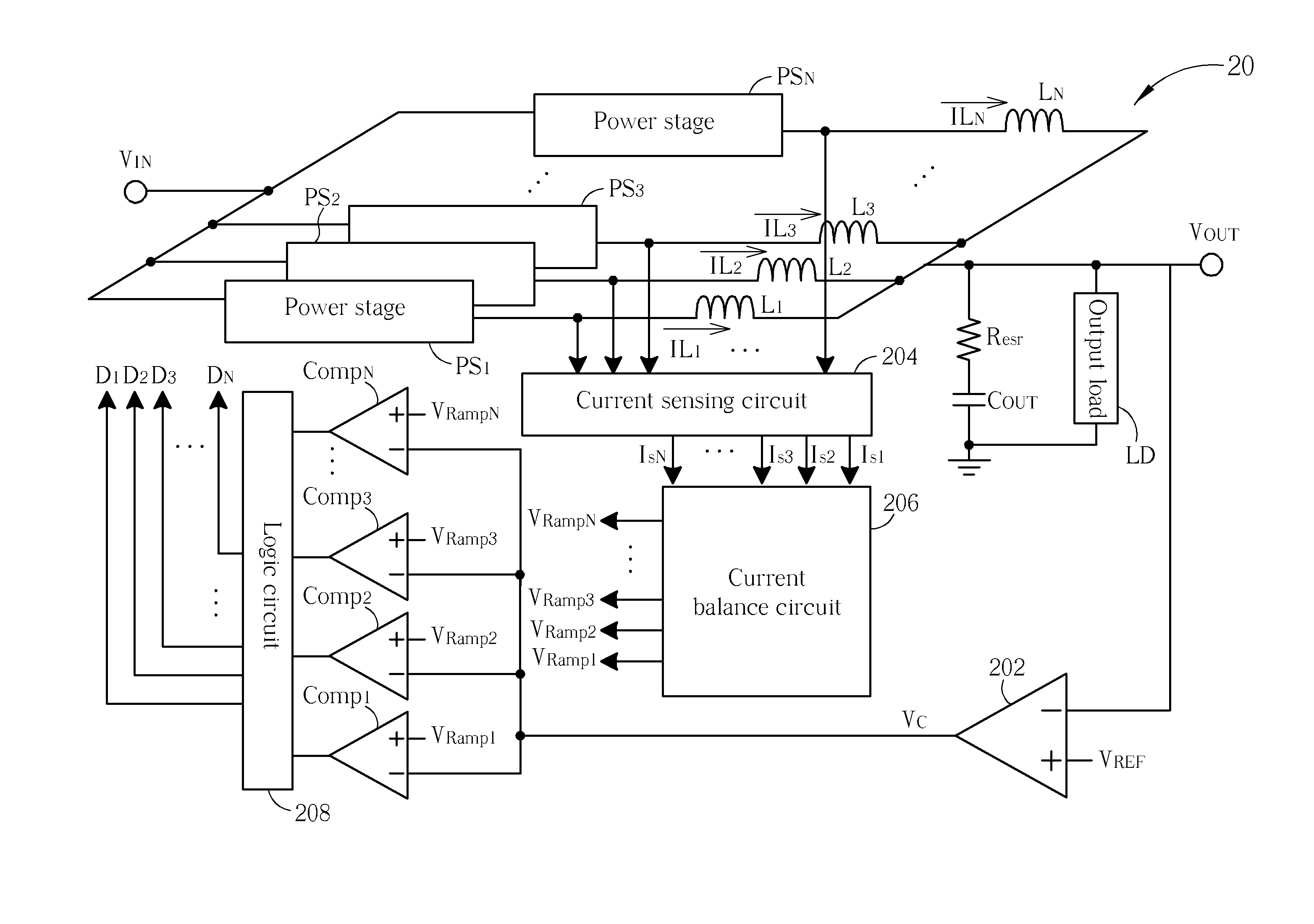
[0025]Please refer to FIG. 2, which is a schematic diagram of a multiphase DC-DC converter 20 according to an embodiment of the present invention. As shown in FIG. 2, the multiphase DC-DC converter 20 has N channels outputting inductor currents IL1˜ILN to an output load LD. The multiphase DC-DC converter 20 includes power stages PS1˜PSN, an error amplifier 202, a current sensing circuit 204, a current balance circuit 206, comparators Comp1˜CompN, and a logic circuit 208.

[0026]In short, in the voltage-controlled multiphase DC-DC converter 20, each power stage among the power stages PS1˜PSN includes a high-side power transistor and a low-side power transistor, respectively, which can be turned on and off by means of pulse width modulation (PWM) according to duty cycles D1˜DN, to charge a capacitor COUT with an input voltage VIN through inductors L1˜LN and a resistor Resr, so as to generate an output voltage VOUT for the output load LD. The error amplifier 202 amplifies a difference be...


PUM


Abstract

The present invention discloses a current balance circuit for a multiphase DC-DC converter. The current balance circuit comprises a current error calculation circuit, for generating a plurality of current balance signals indicating imbalance levels of a plurality of inductor currents of a plurality of channels of the multiphase DC-DC converter according to a plurality of current sensing signals of the plurality of channels, a time shift circuit, for adjusting pulse widths of a plurality of clock signals according to the plurality of current balance signals, and a ramp generator, for deciding shift levels of a plurality of ramp signals according to the plurality of clock signals.

Description

BACKGROUND OF THE INVENTION[0001]1. Field of the Invention[0002]The present invention relates to a current balance circuit and a multiphase DC-DC converter and a current balance method thereof, and more particularly, to a current balance circuit and a multiphase DC-DC converter and a current balance method thereof capable of shifting a time of starting to increase a voltage of a ramp signal to perform the current balance, so as to maintain a slope and amplitude of the ramp signal to be constant to prevent a loop gain of the current balance technique from varying with output and input voltages.[0003]2. Description of the Prior Art[0004]With the electronic products developing rapidly, requirements for specification on power management chips of the electronic products become more rigorous, especially on those for the microprocessors with high performance. In addition to high efficiency, the power management chips are also required to have an extreme high current driving capability and ...

Claims


Application Information

Patent Timeline
Patent Type & Authority Applications(United States)
IPC IPC(8): G05F1/46
CPCH02M1/084H02M3/1584H02M1/0025H02M3/1586
Inventor CHEN, KE-HORNGKUO, YUEH-LUNGSU, CHIH-HENGSU, YI-PINGHUANG, YU-PINGLEE, YU-HUEI
Owner ANPEC ELECTRONICS CORPORATION
Why Eureka
Try Eureka