Output Current Estimation for an Isolated Flyback Converter With Variable Switching Frequency Control and Duty Cycle Adjustment for Both PWM and PFM Modes

a flyback converter and output current estimation technology, applied in the field of flyback converters, can solve the problems of relatively high cost of opto-isolators and inability to integrate well with integrated circuits

Inactive Publication Date: 2013-11-07
HONG KONG APPLIED SCI & TECH RES INST
View PDF3 Cites 138 Cited by
  • Summary
  • Abstract
  • Description
  • Claims
  • Application Information

AI Technical Summary

Problems solved by technology

Opto-isolators have been used to isolate the control circuitry, but these opto-isolators are relatively expensive and do not integrate well with integrated circuits (IC's).

Method used


Image

  • Output Current Estimation for an Isolated Flyback Converter With Variable Switching Frequency Control and Duty Cycle Adjustment for Both PWM and PFM Modes
  • Output Current Estimation for an Isolated Flyback Converter With Variable Switching Frequency Control and Duty Cycle Adjustment for Both PWM and PFM Modes
  • Output Current Estimation for an Isolated Flyback Converter With Variable Switching Frequency Control and Duty Cycle Adjustment for Both PWM and PFM Modes

Examples


Embodiment Construction

[0018]The present invention relates to an improvement in power converters. The following description is presented to enable one of ordinary skill in the art to make and use the invention as provided in the context of a particular application and its requirements. Various modifications to the preferred embodiment will be apparent to those with skill in the art, and the general principles defined herein may be applied to other embodiments. Therefore, the present invention is not intended to be limited to the particular embodiments shown and described, but is to be accorded the widest scope consistent with the principles and novel features herein disclosed.

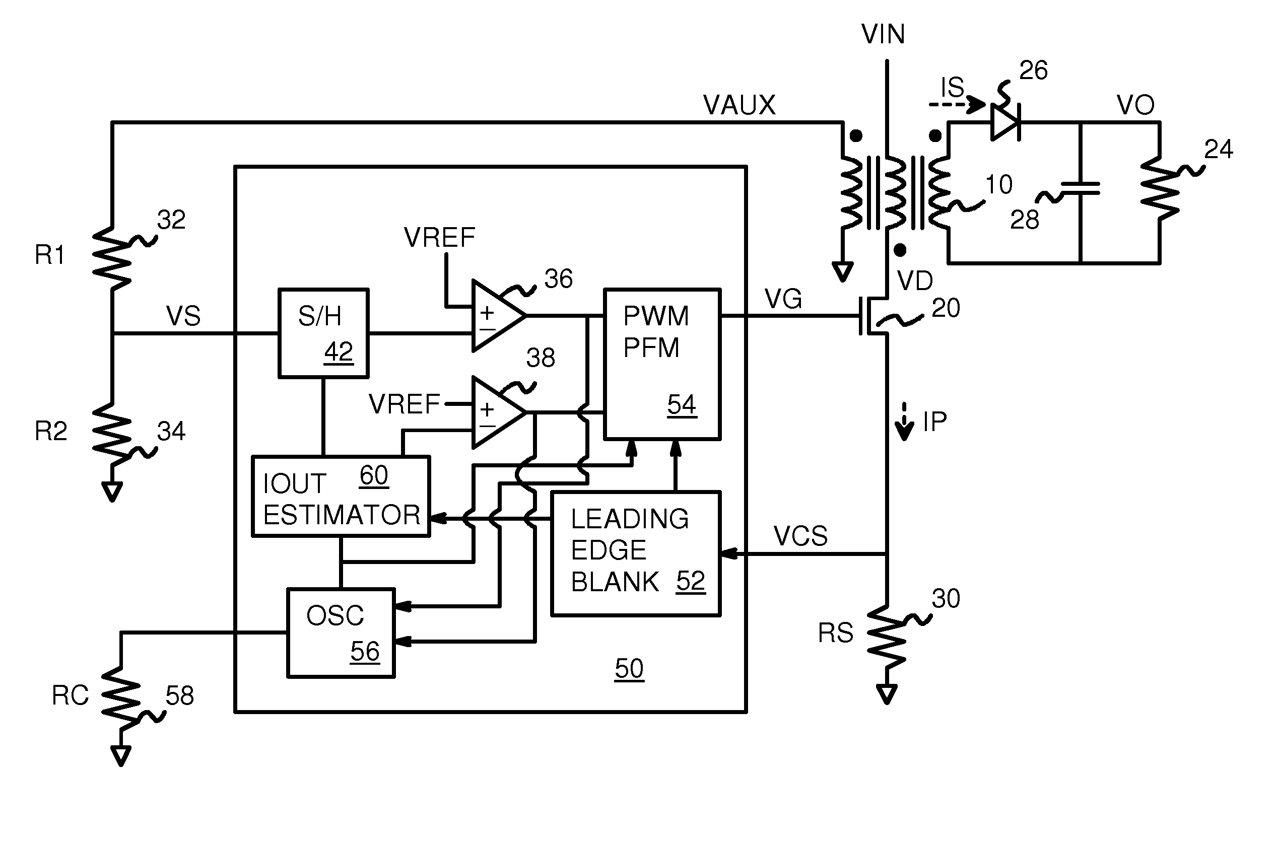
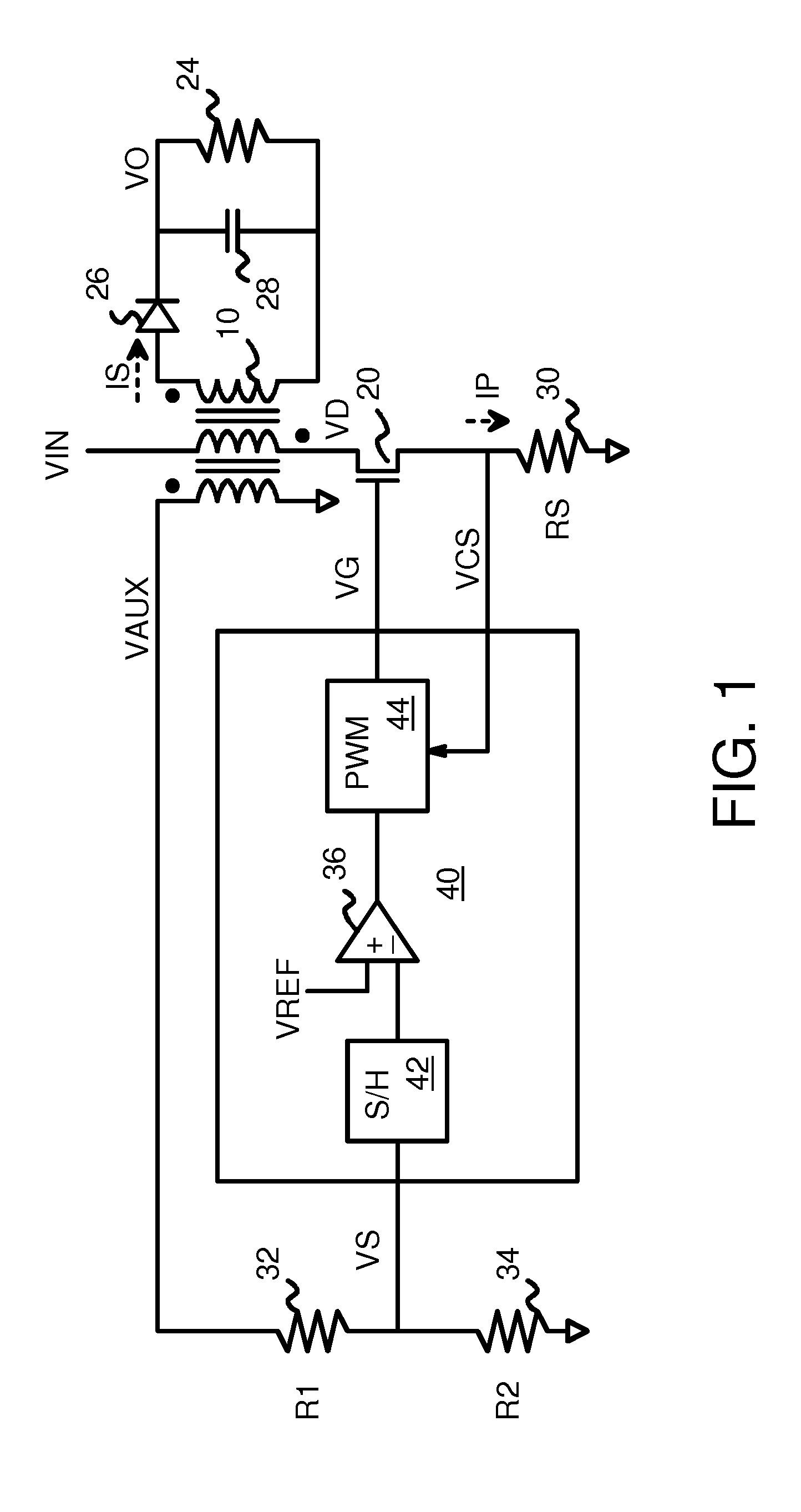
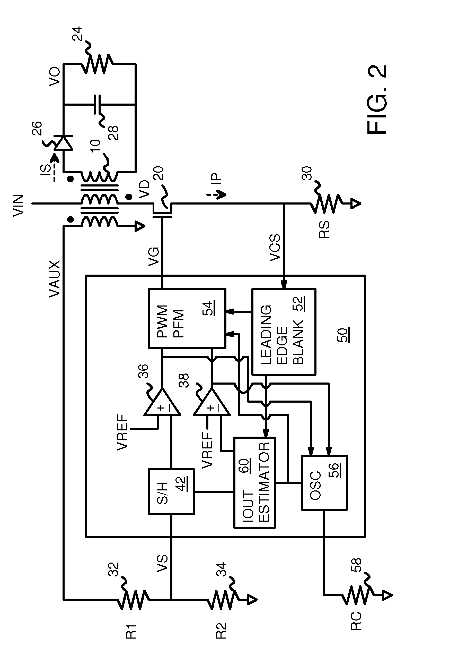
[0019]FIG. 1 shows a diagram of a simplified fly-back converter that switches the primary current. An AC supply produces an alternating-current that is applied to a full-wave rectifier bridge of diodes to generate an input voltage VIN. Alternately, VIN may be a DC source that is not generated from AC.

[0020]Transformer 10 can have an ...


PUM


Abstract

A fly-back power converter has a current-estimating control loop that senses the primary output current in a transformer to control the secondary output. A primary-side control circuit switches primary current through the transformer on and off. A discharge time when a secondary current through an auxiliary winding of the transformer is flowing is generated by sampling a voltage divider on an auxiliary loop for a knee-point. A normalized duty cycle is calculated by multiplying the discharge time by a current that is proportional to the switching frequency and comparing to a sawtooth signal having the switching frequency. The peak of a primary-side voltage is sensed from the primary current loop and converted to a current and multiplied by the normalized duty cycle to generate an estimated current. An error amp compares the estimated current to a reference to adjust the oscillator frequency and peak current to control primary switching.

Description

RELATED APPLICATION[0001]This application is related to the co-pending application for “Constant-Current Control Module using Inverter Filter Multiplier for Off-line Current-Mode Primary-Side Sense Isolated Flyback Converter”, U.S. Ser. No. 12 / 718,707, filed Mar. 5, 2010.FIELD OF THE INVENTION[0002]This invention relates to power converters, and more particularly to fly-back converters with primary side regulation.BACKGROUND OF THE INVENTION[0003]Power converters are useful in many applications, such as converting Alternating-Current (AC) from a power outlet to Direct Current (DC) for use in electronic devices. In cathode-ray tubes (CRT's), a fly-back inverter was used to block the electron beam when the raster dot was retracing or flying back to the beginning on the next raster line in the display. This class of power converters is still known as a fly-back converter, even though they are used in many non-CRT applications, such as for driving light-emitting diodes (LED's) and charg...

Claims


Application Information

Patent Timeline
Patent Type & Authority Applications(United States)
IPC IPC(8): H02M3/335H02M11/00G05F1/10
CPCH02M3/33507H02M1/0009
Inventor KWAN, HING KIT
Owner HONG KONG APPLIED SCI & TECH RES INST
Why Eureka
Try Eureka