
Magnetically tracked surgical needle assembly

a needle assembly and magnetic tracking technology, applied in the field of magnetically tracked needle assembly, can solve the problems of increasing the complexity and time required to manufacture the sensor assembly, the inability of prior art tracking systems to correct small manufacturing errors, and the inability to accurately measure the accuracy of the needle assembly, so as to reduce assembly labor and reduce the cost. , the effect of reducing the cost of assembly labor

Inactive Publication Date: 2013-11-07
ASCENSION TECH
View PDF3 Cites 96 Cited by
  • Summary
  • Abstract
  • Description
  • Claims
  • Application Information

AI Technical Summary

Benefits of technology

The invention is a sensor assembly that is cost-effective and disposable. It reduces the labor and material costs associated with traditional sensor assemblies, allowing for single-use protocols and eliminating the need for repeated sterilization. The invention also includes a single-use disposable needle configuration, reducing the need for repeated sterilization. Additionally, the invention addresses the issue of angular misalignment caused by tolerances in the fit between the sensor assembly and the elongated instrument or stylet.

Problems solved by technology

Such precision increases the complexity and the time required to manufacture the sensor assembly.
These prior art tracking system usually do not provide a way to correct small manufacturing errors which are outside of the allowed positioning tolerances.
Prior art tracking systems also do not provide a way for correcting the angular misalignment caused by tolerances in the sliding fit between the sensor assembly and the elongated instrument.
This orientation error is generally greater than that inherent in the magnetic tracking system and results in the system displaying an incorrect trajectory for the instrument.
Medical procedures are increasingly cost driven.
Magnetic tracking, while improving procedure outcomes, adds a cost element to the equipment.
Labor cost associated with assembly and test of needle increases with design and process complexity.
Overhead costs associated with serial number traceability maintenance of this needle assembly sensor calibration data are hidden, but significant.

Method used


Image

  • Magnetically tracked surgical needle assembly
  • Magnetically tracked surgical needle assembly
  • Magnetically tracked surgical needle assembly

Examples


Embodiment Construction

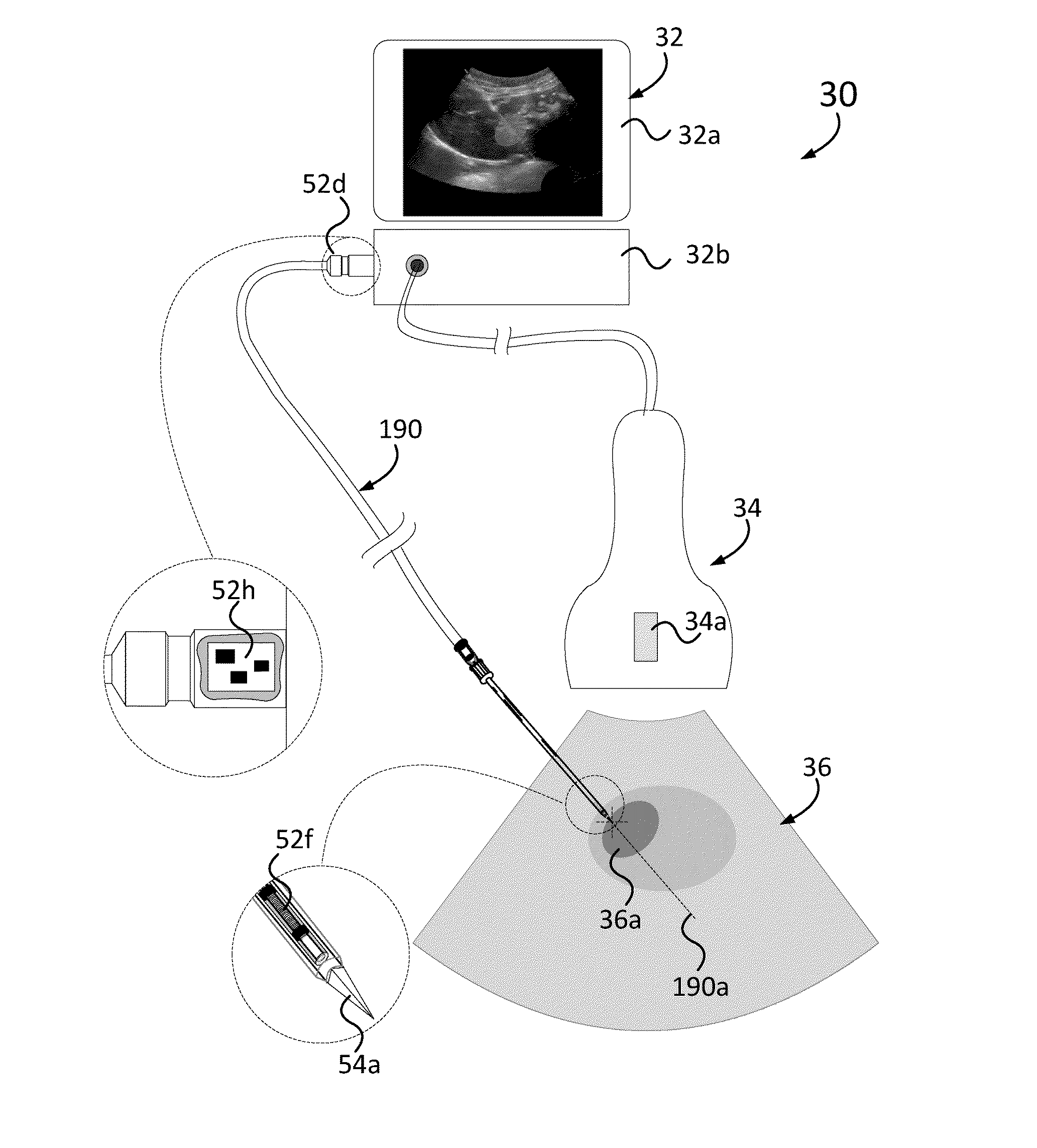
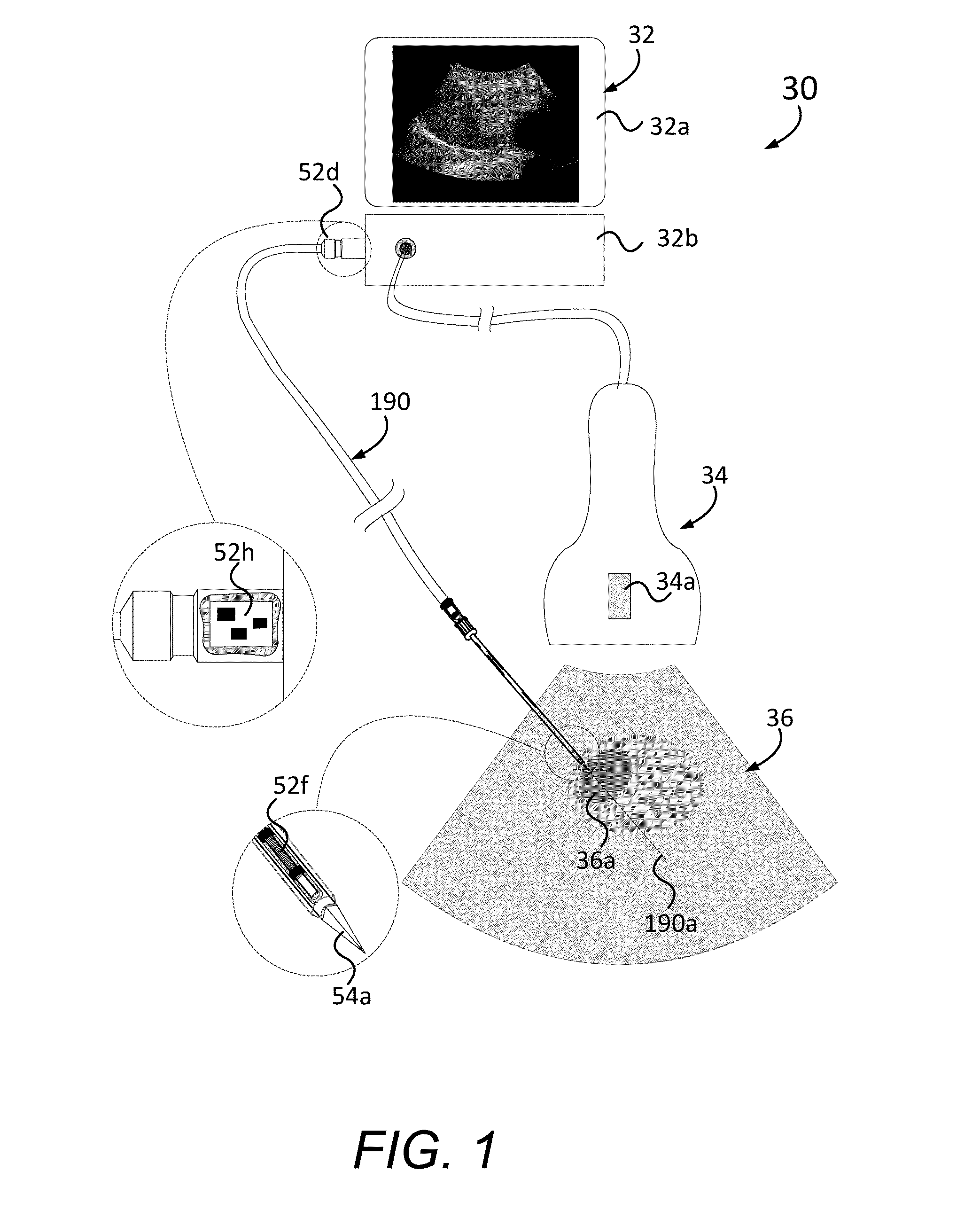
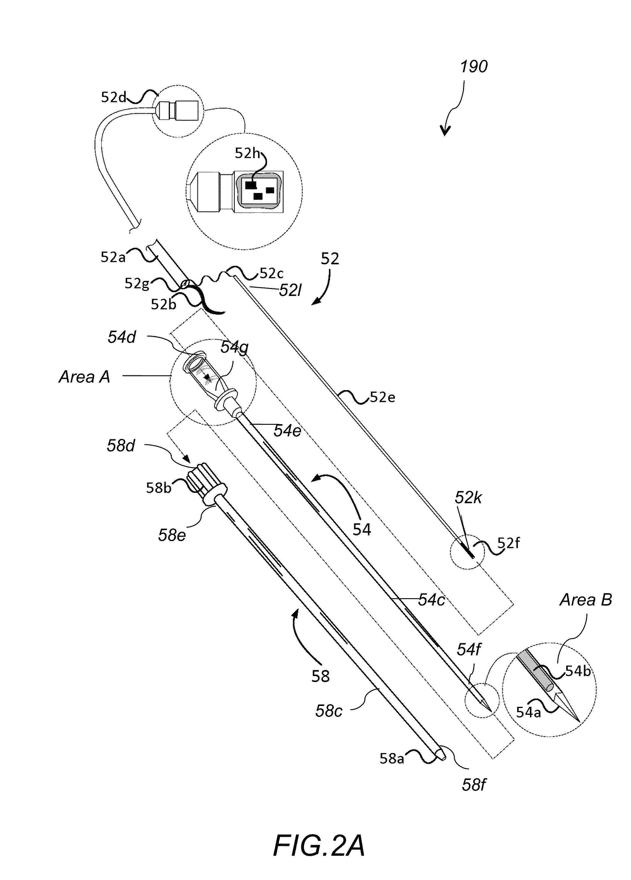
[0036]In a biopsy application, precise knowledge of needle tip position and orientation is critical. In such applications, it is optimal to locate the magnetic sensor as close to the distal end of the needle as is practical, because the needle flexes while penetrating anatomy. Furthermore, care must be taken to ensure that pathogens are not passed from patient to patient using this assembly, thus component sterilization and reprocessing are required if the sensor assembly is to be re-used. A single-use disposable configuration, eliminates the substantial cost to repeatedly sterilize the sensor-assembly. The invention described herein is motivated by the need for a cost-reduced sensor assembly, where costs associated with assembly labor, traceability overhead, high inventory mix, and component materials are minimized. The low cost of the sensor assembly enables a single-use protocol, thus eliminating the procedural cost, borne by the end-user, of repeated sterilization for re-uses.

[0...


PUM


Abstract

An electromagnetic needle tracking system includes a needle assembly, a calibration system and a computing system. The needle assembly includes a needle stylet and a sensor assembly. The sensor assembly includes a sensor that measures position and angular orientation data when placed within an electromagnetic field. The calibration system measures the sensor's position and angular orientation for a known needle tip position and angular orientation within a calibration fixture and calculates a position offset and an angular orientation offset of the sensor relative to the needle tip position and angular orientation. The computing system computes position and angular orientation data of the needle tip by adding the sensor position offset and angular orientation offset to the measured position and angular orientation data, respectively.

Description

FIELD OF THE INVENTION[0001]The present invention relates to a magnetically tracked needle assembly, and more particularly to a disposable, magnetically tracked needle assembly, that includes a sensor coaxially inserted into a disposable stylet.BACKGROUND OF THE INVENTION[0002]Magnetic tracking of instruments with respect to imaged anatomy is widely employed in medical practice. Imaging systems that are enhanced with magnetic tracking may be used to track and display position and orientation of a biopsy needle assembly relative to the imaging plane. They help the clinician guide the instrument to a chosen target with reduced error compared to an unguided biopsy needle. Furthermore, the visual representation of the tracked biopsy needle is not constrained to the ultrasound imaging plane, thus enabling the clinician with more freedom of motion.[0003]For magnetic tracking of an instrument, an electromagnetic sensor is included in a location of the instrument. Electromagnetic sensors ar...

Claims


Application Information

Patent Timeline
Patent Type & Authority Applications(United States)
IPC IPC(8): A61B5/05
CPCA61B5/6848A61B5/062A61B2560/0223A61B2562/085A61B2562/12A61B10/0233A61B8/0841A61B17/3478A61B2017/00725A61B17/3403A61B34/20A61B2034/2051A61B2090/378A61B8/4254
Inventor ASHE, WESTLEY
Owner ASCENSION TECH
Learn More