Vibration isolating device

a technology of vibration isolation and isolating device, which is applied in the direction of cosmonautic vehicles, machine supports, other domestic objects, etc., can solve the problems of only being effective within a small frequency domain, inoperable on low-frequency disruption, and difficult to realize flexible hinge joints designed to withstand mechanical loads at launch

Active Publication Date: 2013-11-14
AIRBUS DEFENCE & SPACE
View PDF19 Cites 19 Cited by
  • Summary
  • Abstract
  • Description
  • Claims
  • Application Information

AI Technical Summary

Benefits of technology

[0027]The material, shape and size of the elastomeric elements of the bars are also preferably calculated such that their bending stiffness is negligible, so as to provide a ball-joint function for the bars.
[0030]and also to solve the problem of isostaticity of the lattice of bars, by increasing the degrees of freedom of rotation to at least one root (flexible ball-joint effect).

Problems solved by technology

Such devices are efficient in regards to high-frequency disturbances, but are inoperative on low-frequency disruptions, which may even be amplified in certain circumstances (in particular in frequency bands close to the resonance frequencies of the suspension).
However, these systems are only effective within a small frequency domain, characterized by the bandwidth of the active control.
One of the major difficulties inherent to this design comes from this requirement for isostatic conditions within the active lattice.
It is well known that it is very difficult to realize flexible hinge joints designed to withstand the mechanical loads at launch.
This type of isolation device, which is both passive and active by superimposition of known elements, has certain limitations.
Firstly, the device does not allow the different elements required for isolation to be incorporated optimally, because the isolation functions are physically separated.
Secondly, it does not allow flexible hinge joints providing the required isostatic conditions to be manufactured easily.

Method used


Image

  • Vibration isolating device
  • Vibration isolating device
  • Vibration isolating device

Examples


Embodiment Construction

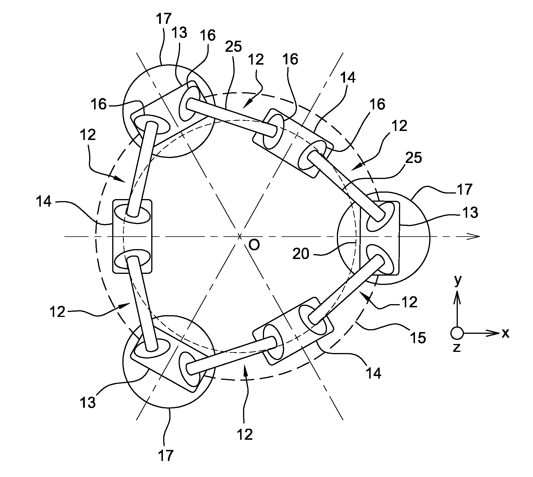
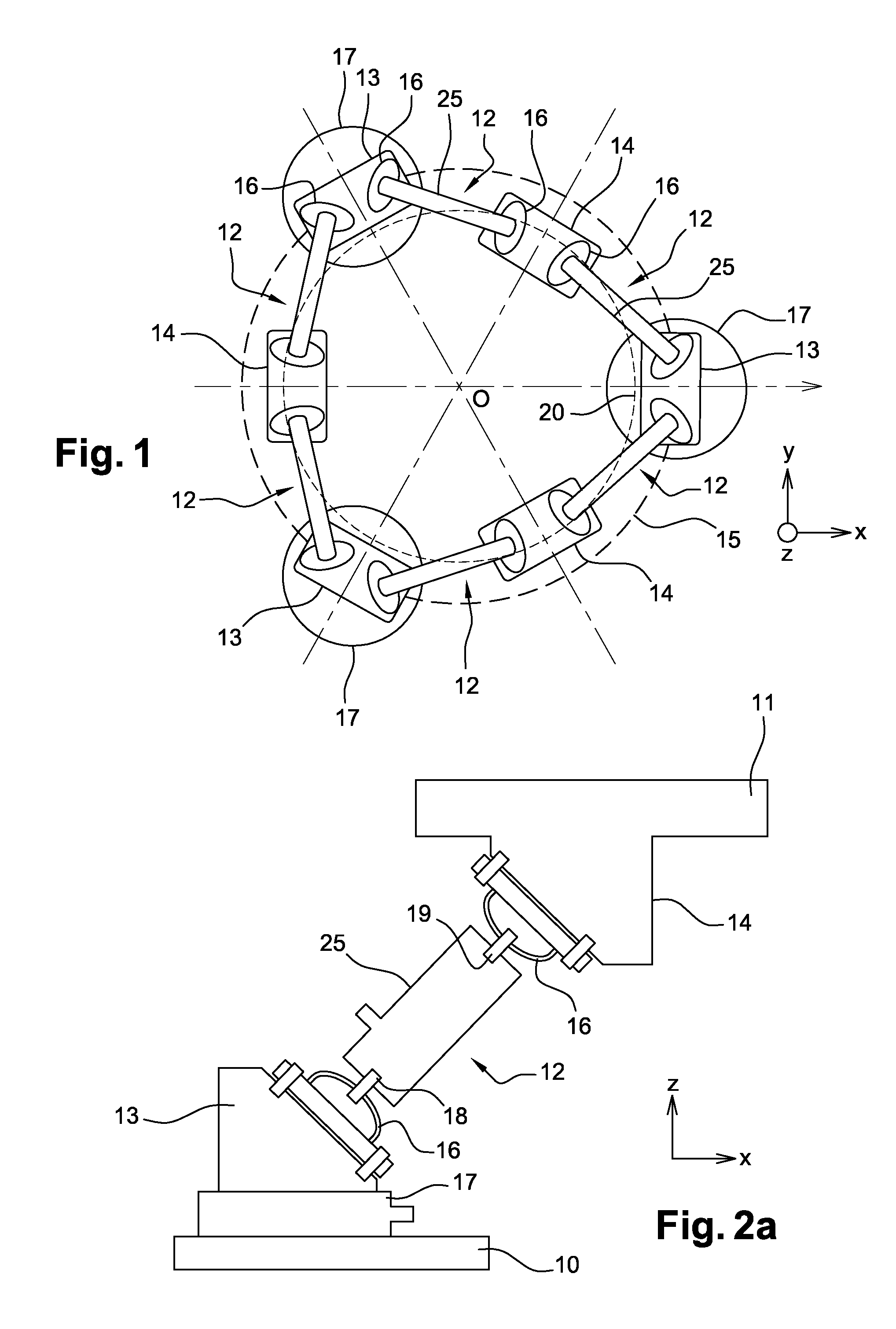
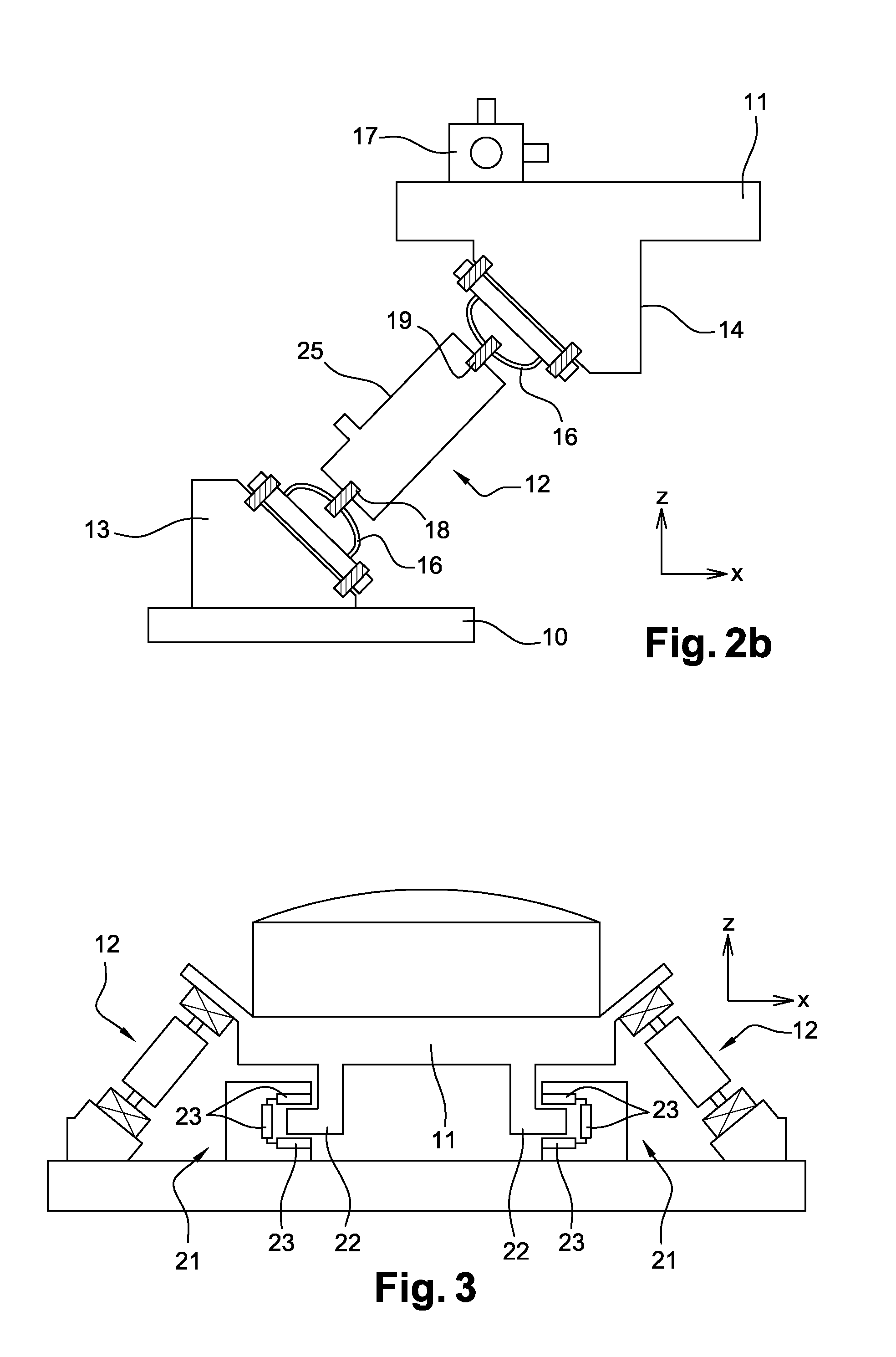
[0019]To this end, the invention envisages a vibration isolation device designed to be positioned between a load-bearing structure and an anchor plate on which a piece of equipment is fastened. In a first usage case, the equipment is a disruptive element that generates vibrations. The device must attenuate the vibrations transmitted to the structure. In a second usage case, the equipment is an element sensitive to vibrations. The device must attenuate, in the vicinity of the sensitive equipment, the vibrations generated by a disruptive element positioned on the load-bearing structure, where these vibrations are propagated to the equipment by the structure.

[0020]The device comprises a lattice made of bars, with each bar comprising at least one axial actuator, with at least one end-fitting of each bar consisting of an element made of elastomeric material (called “elastomeric element”).

[0021]If the bars have only one elastomer end-fitting, the end-fittings are all positioned on the sam...


PUM


Abstract

A vibration isolation device designed to be positioned between a structure (10) and an equipment anchor plate (11), includes a lattice made of bars, with each bar including at least one axial actuator (25), the lattice being an active hexapod including six identical isolation bars (12) positioned according to a regular geometry, the six bars (12) being arranged such that the control of the tension-compression forces in each of the six bars (12) makes possible the force and torque control of six separate degrees of freedom at the interface between the structure and the equipment, so as to produce effective isolation along all the system's degrees of freedom. At least one end-fitting of each bar consists of an element (16) made of elastomeric material (called “elastomeric element”).

Description

[0001]This invention relates to a vibration isolating device. It relates more specifically to the field of isolating micro-vibrations.BACKGROUND OF THE INVENTION AND PROBLEM STATEMENT[0002]Some satellites comprise equipment that generates vibratory disruptions, which can be transmitted by the structure to payload elements sensitive to these disturbances. This is about isolating disruptive equipment by adequate devices that attenuate the vibrations they transmit to the load-bearing structure and / or isolating sensitive elements from the disturbances generated by using the same type of devices.[0003]In the field of isolating equipment that generates disruptions or sensitive elements from vibrations, several types of solution are currently known.[0004]A first family of solutions utilizes passive, i.e. inert, isolators usually taking the form of elastomer blocks, strips, springs, etc. Such devices are efficient in regards to high-frequency disturbances, but are inoperative on low-frequen...

Claims


Application Information

Patent Timeline
Patent Type & Authority Applications(United States)
IPC IPC(8): F16F15/08B64G1/38
CPCF16F15/08B64G1/38B64G1/66B64G1/641B64G1/228
Inventor LAURENS, PHILIPPE
Owner AIRBUS DEFENCE & SPACE
Why Eureka
Try Eureka