Electrical feedthroughs for nuclear reactor

a technology of nuclear reactors and electrical feedthroughs, applied in the field of nuclear reactor arts, nuclear power generation arts, nuclear reactor instruments, etc., can solve the problems of unisolable primary leakage, uncovered core, and requiring reactor shutdown

Active Publication Date: 2013-11-14
BWXT MPOWER INC
View PDF4 Cites 11 Cited by
  • Summary
  • Abstract
  • Description
  • Claims
  • Application Information

AI Technical Summary

Problems solved by technology

Generally, a guide tube contains either a control rod or an instrument but not both, due to space limitations.
Locating these instruments in the reactor core, or anywhere in the vessel, is a challenge because the reactor vessel contains high temperature and high pressure water and the core produces radiation, an inhospitable environment for electronics.
A problem with this approach is that a failure of a conduit or a seal table connection can cause an unisolable primary leak.
Although the resulting leak would be small and within the capacity of the coolant charging pumps, it may still necessitate

Method used


Image

  • Electrical feedthroughs for nuclear reactor
  • Electrical feedthroughs for nuclear reactor
  • Electrical feedthroughs for nuclear reactor

Examples


Embodiment Construction

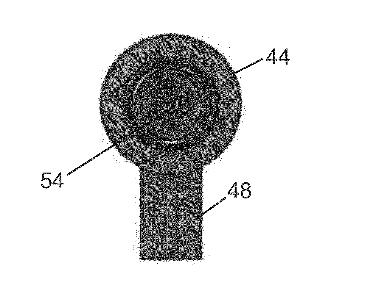
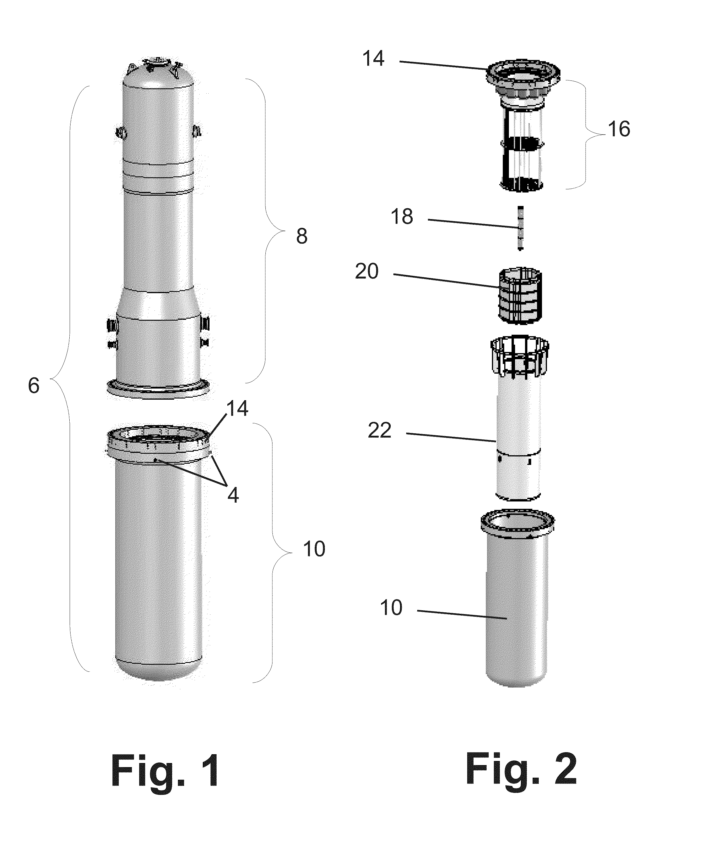
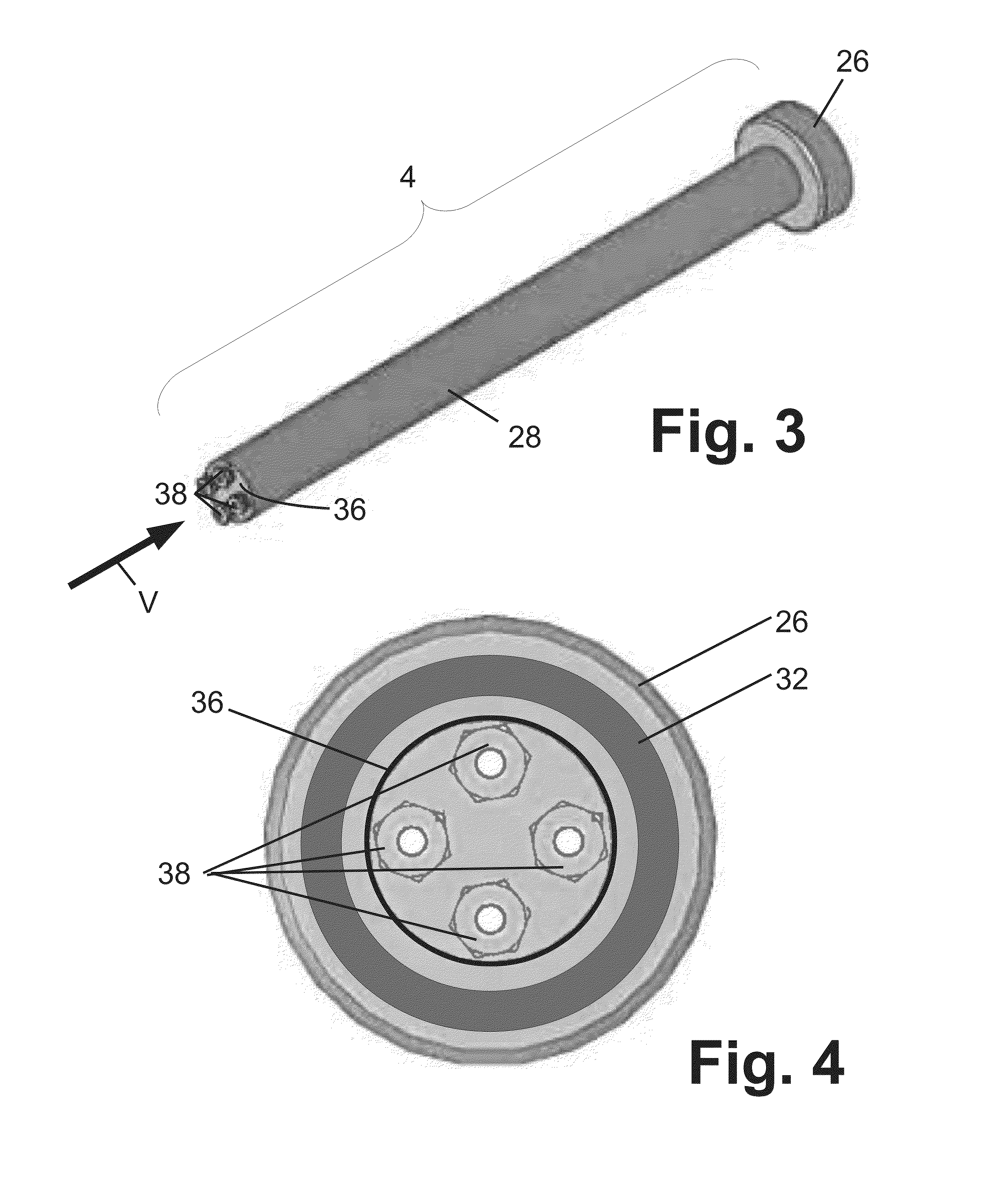
[0024]FIG. 1 illustrates an integral reactor pressure vessel 6 including an upper vessel 8 and a lower vessel 10. The vessel portions 8, 10 are joined at a mid-flange 14 during operation, but FIG. 1 shows the upper vessel 8 lifted off the lower vessel / midflange 10, 14 (e.g., for refueling). which are shown separated in FIG. 1. The lower vessel 10 includes illustrative feedthroughs 4. In an integral reactor, the vessel houses the reactor core, reactor internals, and steam generator in a common pressure boundary, i.e. in the pressure vessel 6. The integral reactor of FIG. 1 is designed so that the upper vessel 8 contains the steam generators and may be removed as a unit (including the steam generators) for refueling.

[0025]A common design goal for any reactor is to minimize the number of reactor vessel penetrations, but penetrations cannot be completely avoided as core components must have electrical, hydraulic, and instrumentation lines enter the reactor. Examples of core components t...


PUM


Abstract

A nuclear reactor includes a nuclear reactor core comprising fissile material and a pressure vessel containing the nuclear reactor immersed in primary coolant water at an operating pressure. The pressure vessel has a vessel penetration passing through a wall of the pressure vessel. An electrical feedthrough seals the vessel penetration and has an outside electrical connector mounted at the pressure vessel. The outside electrical connector is at atmospheric pressure. The electrical feedthrough may include a flange disposed inside the pressure vessel and sealing against an inside surface of the wall of the pressure vessel. The outside electrical connector of the electrical feedthrough may be inset into the wall of the pressure vessel.

Description

[0001]This application claims the benefit of U.S. Provisional Application No. 61 / 625,378, filed Apr. 17, 2012. U.S. Provisional Application No. 61 / 625,378, filed Apr. 17, 2012 is hereby incorporated by reference in its entirety into the specification of this application.BACKGROUND[0002]The following relates to the nuclear reactor arts, nuclear power generation arts, nuclear reactor instrumentation arts, nuclear vessel feedthrough arts, and related arts.[0003]In nuclear reactor designs of the integral pressurized water reactor (integral PWR) type, a nuclear reactor core is immersed in primary coolant water at or near the bottom of a pressure vessel. In a typical design, the primary coolant is maintained in a subcooled liquid phase in a cylindrical pressure vessel that is mounted generally upright (that is, with its cylinder axis oriented vertically). A hollow cylindrical central riser is disposed concentrically inside the pressure vessel. Primary coolant flows upward through the reac...

Claims


Application Information

Patent Timeline
IPC IPC(8): G21C13/036G21C7/12
CPCG21C13/036G21C7/12G21C17/116G21C1/32Y02E30/30
Inventor BERTHOLD, MICHAEL S.SHARGOTS, SCOTT J.
Owner BWXT MPOWER INC
Why Eureka
Try Eureka