Method and Device for Operating Compressed-Air Brakes

a brake and compressed air technology, applied in the direction of braking systems, instruments, analogue processes for specific applications, etc., can solve the problems of leakage of compressed air systems of brakes, for example in lines or brake cylinders, and achieve the effect of detecting leakage in the compressed air system of brakes

Inactive Publication Date: 2013-11-14
WABCO GMBH
View PDF0 Cites 16 Cited by
  • Summary
  • Abstract
  • Description
  • Claims
  • Application Information

AI Technical Summary

Benefits of technology

[0017]The present invention accordingly comprises the various steps and the relation of one or more of such steps with respect to each of the others, and embodies features of construction, combination

Problems solved by technology

As a result, leaks in the compressed air system of the brake, for exam

Method used


Image

  • Method and Device for Operating Compressed-Air Brakes
  • Method and Device for Operating Compressed-Air Brakes
  • Method and Device for Operating Compressed-Air Brakes

Examples


Embodiment Construction

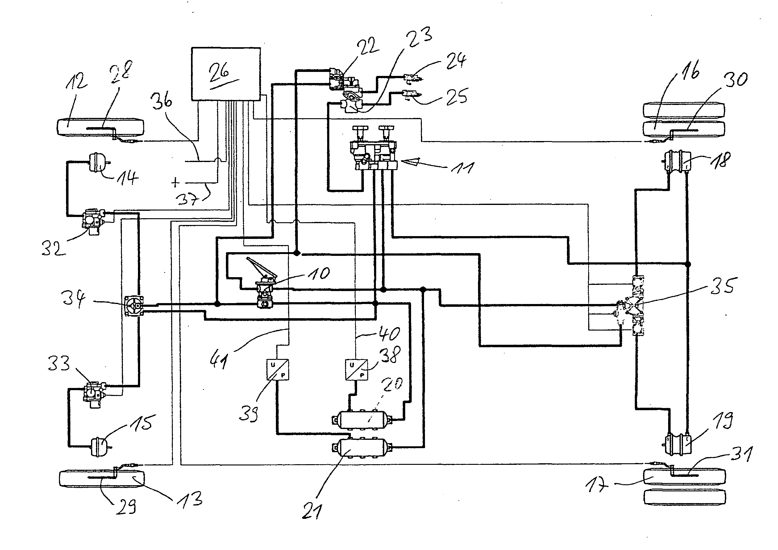
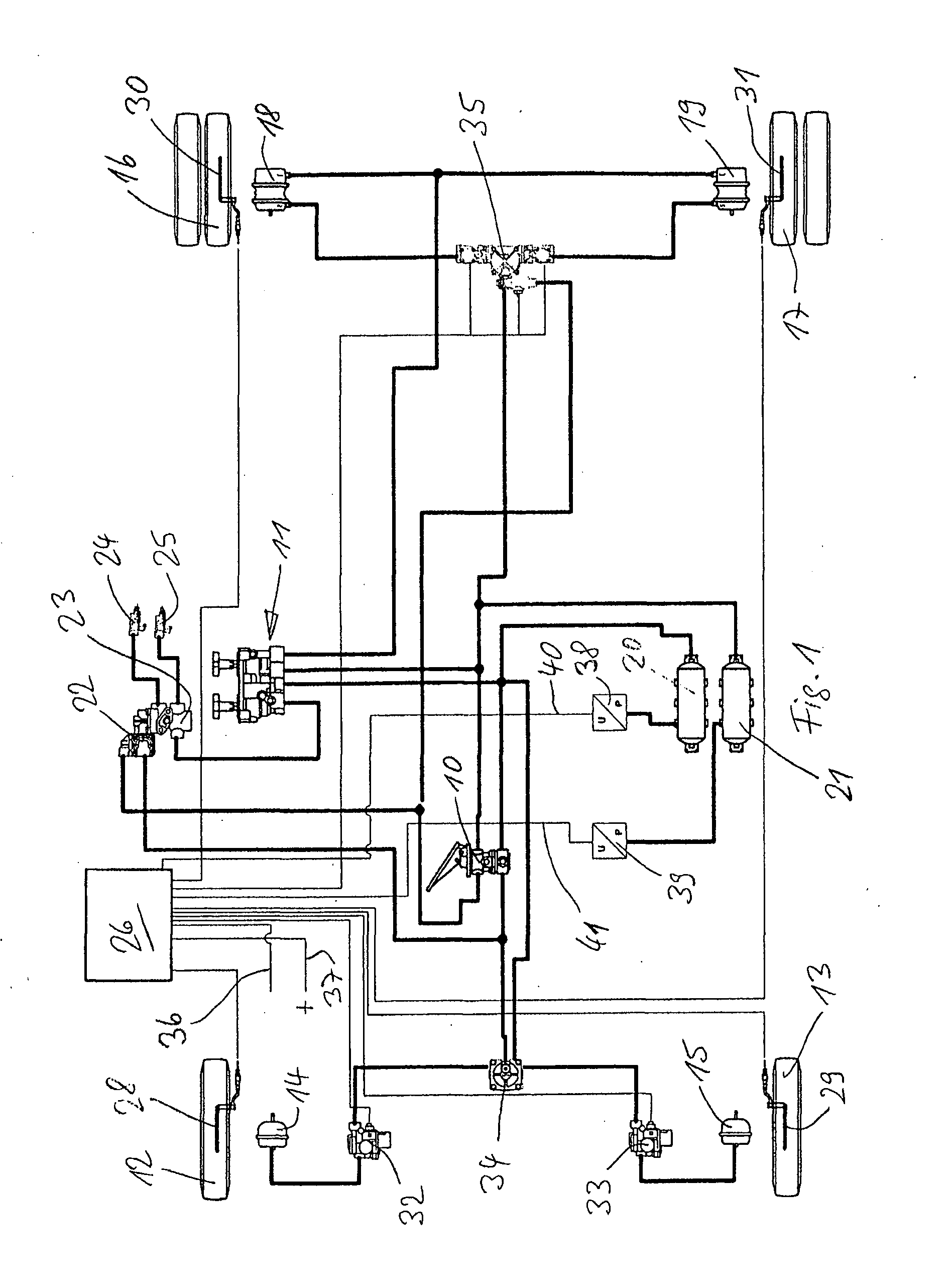
[0060]Referring now to the drawing figures, FIG. 1 shows a pneumatic brake system for a motor vehicle having two axles and including a foot brake valve 10, a handbrake valve 11, one brake cylinder 14, 15 per front wheel 12, 13, one brake cylinder 18, 19 per rear wheel 16, 17 (as twin tires here), with a parking brake function, as well as two compressed air containers 20, 21 for two separate brake circuits. Valves 22, 23 and ports 24, 25 are provided for a trailer (not shown). The specified parts are connected to one another via compressed air lines. The assemblies for generating and conditioning the compressed air are not shown in FIG. 1.

[0061]A closed-loop braking intervention control of the ABS type and / or within the scope of an EBS is assigned to the pneumatic brake system. A brake control device 26 is present for this brake system. The brake control device 26 receives signals directly from wheel speed sensors 28, 29 (at the front wheels) and wheel speed sensors 30, 31 (at the re...


PUM


Abstract

A method and brake control device, with closed-loop braking intervention control functionality, for operating a vehicle compressed-air brake system includes directly processing data representing at least one pressure measurement of the compressed air, such as the pressure in the brake circuit(s) and/or the system pressure. Brake system leaks can be detected even when the vehicle is operating.

Description

CROSS-REFERENCE TO RELATED APPLICATION[0001]This application claims the benefit of DE 10 2012 009 185 filed on May 10, 2012, the disclosure of which is hereby incorporated herein by reference in its entirety.FIELD OF THE INVENTION[0002]The present invention generally relates to methods and devices for controlling vehicle compressed-air brakes.BACKGROUND OF THE INVENTION[0003]Heavy vehicles such as trucks, with or without trailers, as well as buses etc. are equipped with compressed-air brakes. For safety reasons, a heavy vehicle brake system can have brake circuits that are independent of one another. In many countries, an anti-lock brake system (ABS) is provided as a closed-loop braking intervention control for heavy vehicles. The ABS is controlled by a separate electronic brake control device. Such a control device can also be provided in vehicles for other purposes and is referred to as an ECU (electronic control unit). The ECU provided for the ABS typically evaluates only the dat...

Claims


Application Information

Patent Timeline
IPC IPC(8): B60T17/22B60T13/66
CPCB60T17/221B60T13/66B60T13/662
Inventor FEYERABEND, KONRADSTRUWE, OTMAR
Owner WABCO GMBH
Why Eureka
Try Eureka