

Variable compression ratio internal combustion engine
a compression ratio and internal combustion engine technology, applied in the direction of engines, machines/engines, mechanical devices, etc., can solve the problems of reducing the reliability or durability of the actuator or the decelerator of the linking mechanism, and achieve the effect of suppressing the vibration of the first control sha
- Summary
- Abstract
- Description
- Claims
- Application Information
AI Technical Summary
Benefits of technology
Problems solved by technology
Method used
Image

Examples
first embodiment
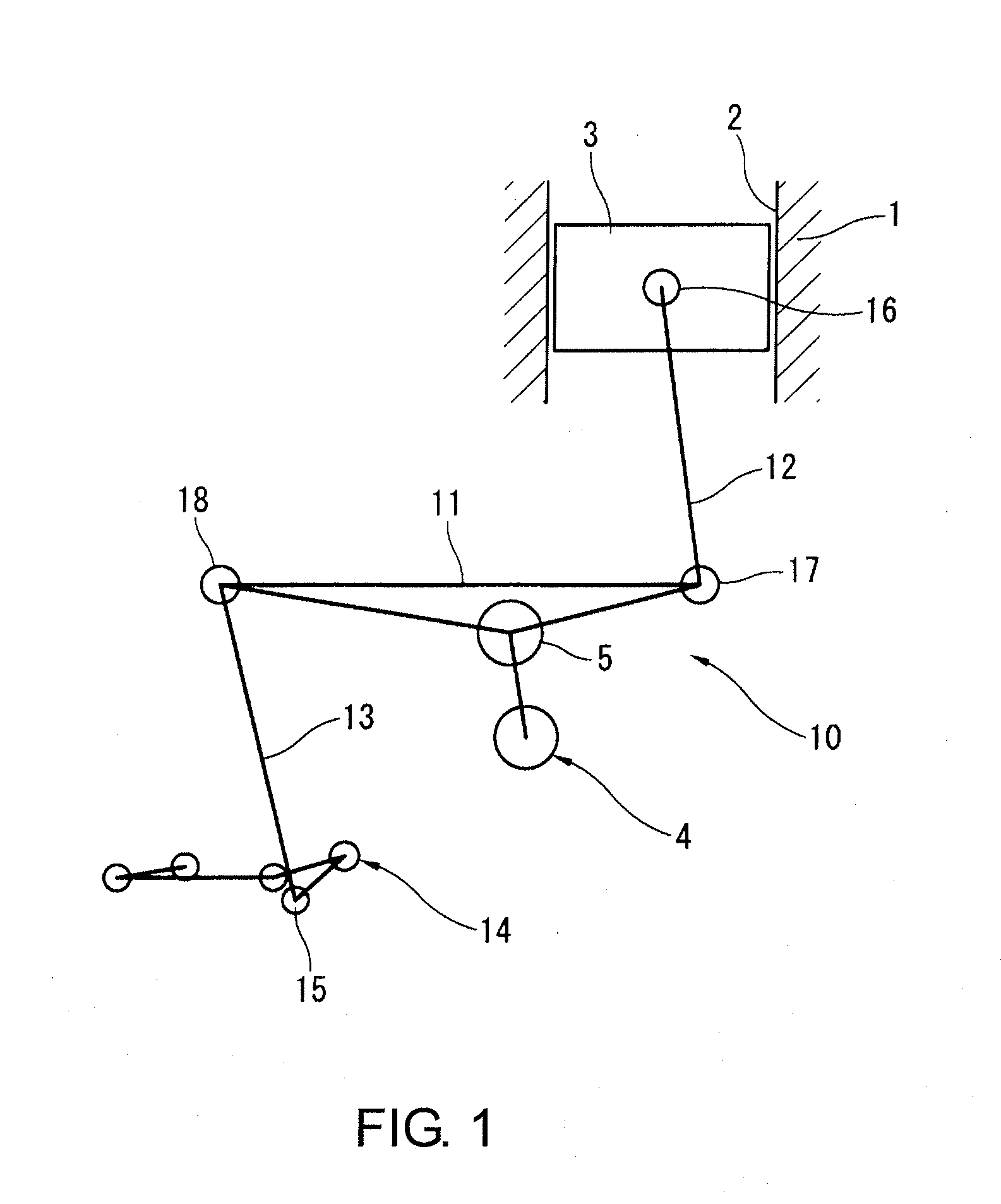
[0023]Referring initially to FIG. 1, a variable compression ratio mechanism using a multiple-link piston crank mechanism is diagrammatically illustrated that is used in connection with in a The variable compression ratio mechanism is a conventionally known mechanism, which is disclosed in various documents such as in Japanese Laid-Open Patent Publication No. 2004-257254 (U.S. Pat. No. 6,920,847). Thus, only a brief description of the variable compression ratio mechanism will be provided herein.
[0024]As seen in FIG. 1, a cylinder block 1 defines a plurality of cylinders 2 (only one shown). The cylinder block 1 constitutes part of a main engine body of an internal combustion engine. A piston 3 is slidably disposed in each of the cylinders 2. A crankshaft 4 is rotatably supported on the cylinder block 1 for moving the pistons 3 (only one shown) within the cylinders 2 (only one shown) in a reciprocating manner. The crankshaft 4 includes a plurality of crank pins 5 (only one shown).
[002...
third embodiment
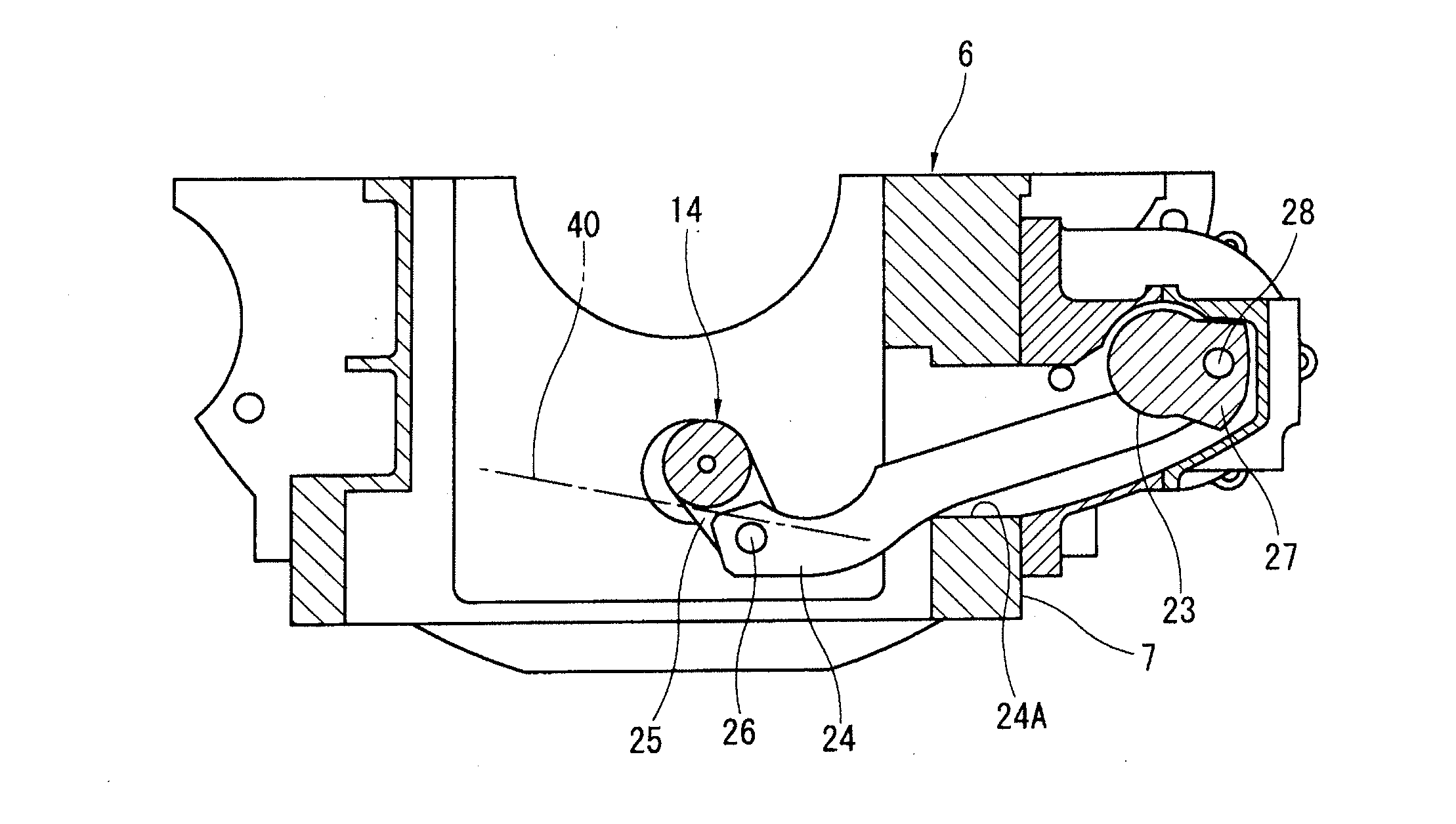
[0043](4) In the third embodiment, as shown in FIG. 7, the axial clearance D5 between the axial side surface of one of the first bearings 32 and the opposing axial side surface of the first control shaft 14 is set greater than an axial clearance D6 between the axial side surface of one of the second bearings 34 and the opposing axial side surface of the second control shaft 23. Thus, setting the axial clearance D6 of the second control shaft to be smaller than the axial clearance D5 of the first control shaft makes it possible to reduce positional misalignment in the thrust direction of the lever 24 whose thrust position (axial position) is established by the second control shaft 23, and also makes it possible to suppress collapsing of the second arm 27 of the second control shaft 23 and consequently to suppress collapsing of the lever 24. Therefore, thrust-direction misalignment in the first control shaft-side portion of the lever 24 can be reduced, whereby vibration of the first c...
seventh embodiment
[0048](9) In the seventh embodiment shown in FIG. 11, a radial clearance D16 between an external peripheral surface of one second journal section 33 and an internal peripheral surface of one of the second bearings 34 is set to be smaller than the radial clearance D15 between an external peripheral surface of one of the first journal sections 31 and an internal peripheral surface of one of the first bearings 32. Although the lever 24 also collapses due to the collapsing of the second control shaft 23 wherein the second control shaft 23 is displaced in a direction inclined relative to the axial direction, because the radial clearance D16 between the second control shaft 23 and the lever 24 is set to be smaller, it is possible to avoid an increase in the amount of collapse in the distal end portion of the lever 24 on the side of the first control shaft 14, and collisions between the first control shaft 14 and the lever 24 can be suppressed or avoided.
[0049](10) Though not illustrated, ...
PUM
 Abstract
Description
Claims
Application Information