
Suspension arm device for vehicle

a suspension arm and vehicle technology, applied in the direction of resilient suspensions, interconnection systems, vehicle components, etc., can solve the problems of reducing the movement of the ball joint to the outside of the vehicle, neither the roll center securing nor the ground kingpin offset securing can be solved

Inactive Publication Date: 2013-11-21
HYUNDAI MOTOR CO LTD
View PDF1 Cites 9 Cited by
  • Summary
  • Abstract
  • Description
  • Claims
  • Application Information

AI Technical Summary

Benefits of technology

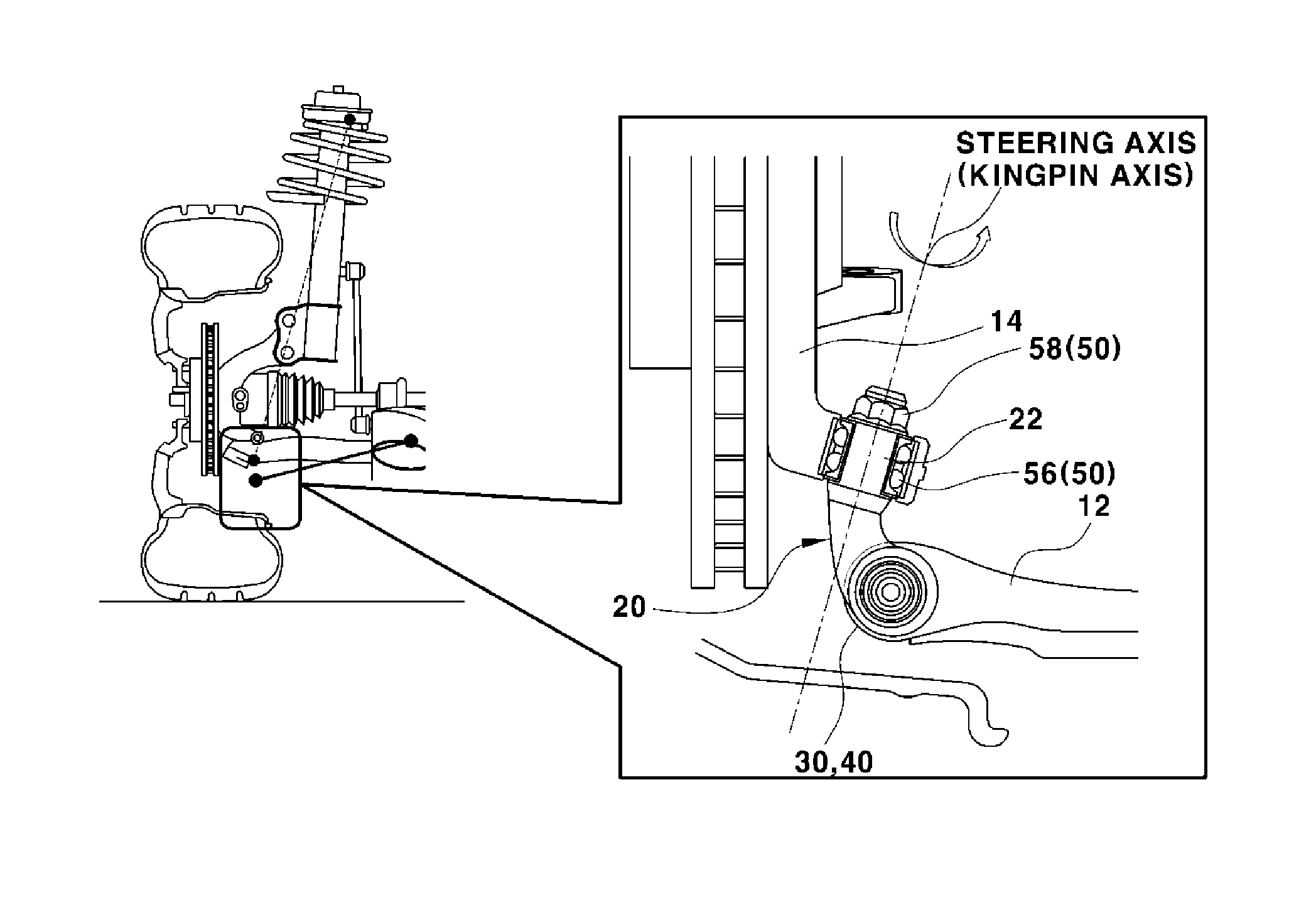
The present invention relates to a device for joining the arms of a vehicle suspension system. The invention provides a solution to problems with previous designs that independently control the movement of the vehicle's wheels during turning and linear driving. The device includes two parts: one that controls the rotation of the wheels during turning and the other that controls the movement of the wheels during linear driving. This allows for better control of the vehicle's roll center height and the optimal position of the steering axis, improving stability and reducing vibration.

Problems solved by technology

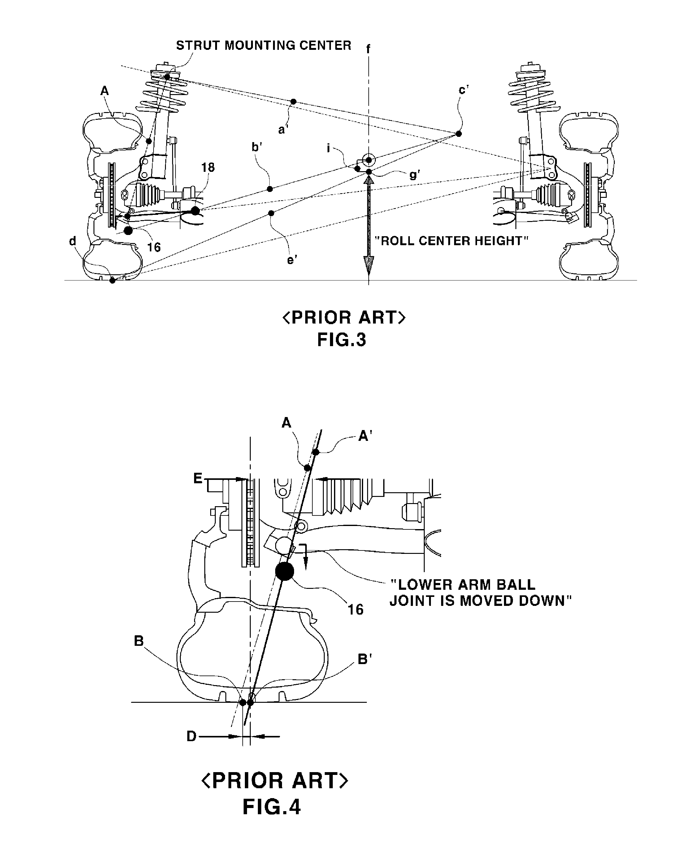
However, if the position of the lower arm ball joint is lowered, the following problems occur.
To solve this problem, the lower arm ball joint has to be moved to the outside of the vehicle, but due to a space restriction with a brake disk, there is also a restriction in movement of the ball joint to the outside of the vehicle, so that neither roll center securing nor ground kingpin offset securing can be solved.

Method used


Image

  • Suspension arm device for vehicle
  • Suspension arm device for vehicle
  • Suspension arm device for vehicle

Examples


Embodiment Construction

[0040]Reference will now be made in detail to various embodiments of the present invention(s), examples of which are illustrated in the accompanying drawings and described below. While the invention(s) will be described in conjunction with exemplary embodiments, it will be understood that present description is not intended to limit the invention(s) to those exemplary embodiments. On the contrary, the invention(s) is / are intended to cover not only the exemplary embodiments, but also various alternatives, modifications, equivalents and other embodiments, which may be included within the spirit and scope of the invention as defined by the appended claims.

[0041]It is understood that the term “vehicle” or “vehicular” or other similar term as used herein is inclusive of motor vehicles in general such as passenger automobiles including sports utility vehicles (SUV), buses, trucks, various commercial vehicles, watercraft including a variety of boats and ships, aircraft, and the like, and i...


PUM


Abstract

A suspension arm jointing device for a vehicle includes a steering axis and a roll center can be independently controlled. By dualizing a joint between a lower arm and a knuckle into a rotation portion based on wheel steering and a rotation portion based on wheel's up / down movement, a lower aim joint's function for determining a roll center height during turning and determination of an steering axis position which affects wheel vibration and braking stability during linear driving can be controlled independently of each other, thereby heightening the roll center and determining an optimal steering axis (kingpin axis) position.

Description

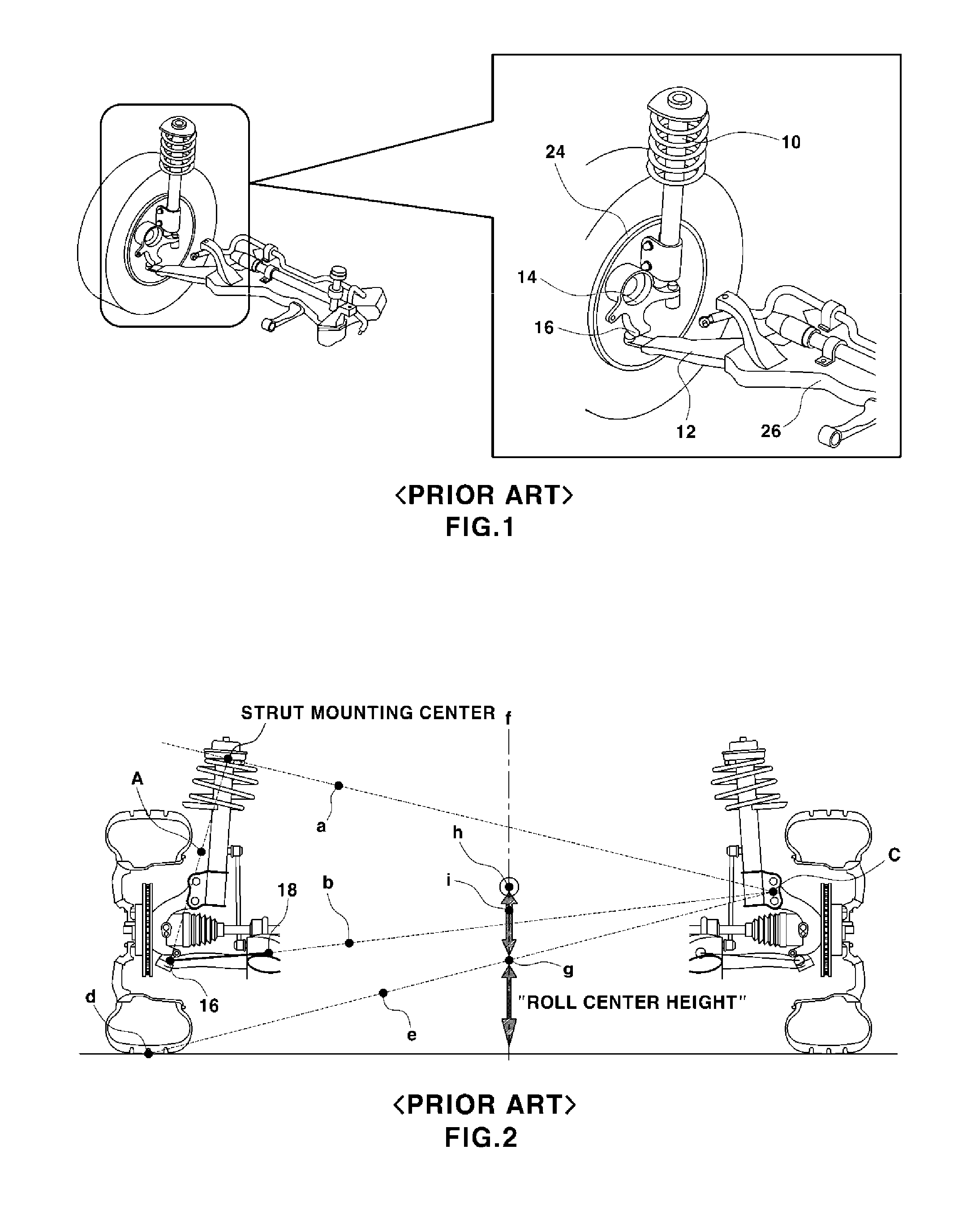
CROSS-REFERENCE TO RELATED APPLICATION[0001]The present application claims priority of Korean Patent Application Number 10-2012-0051293 filed May 15, 2012, the entire contents of which application is incorporated herein for all purposes by this reference.BACKGROUND OF INVENTION[0002]1. Field of Invention[0003]The present invention relates to a suspension arm device for a vehicle. More particularly, the present invention relates to a suspension arm joining device for a vehicle, in which a steering axis and a roll center can be independently controlled.[0004]2. Description of Related Art[0005]A suspension device for a vehicle refers to a device which absorbs a shock delivered to a vehicle body due to an uneven pavement surface and improves ride comfort by adjusting movement of the vehicle body during driving, braking, and turning of the vehicle.[0006]As shown in FIG. 1, the suspension device includes a strut 10 which is a combination of a shock absorber, a spring, a bump stopper, and ...

Claims


Application Information

Patent Timeline
Patent Type & Authority Applications(United States)
IPC IPC(8): B60G3/06
CPCB60G3/06B60G3/20B60G7/008B60G2204/148B60G2204/418B60G2206/50B62D7/18B60G7/04B60G21/05
Inventor HAM, HYEONG SEUNG
Owner HYUNDAI MOTOR CO LTD
Learn More