
Quick Connector

a quick connector and assembly technology, applied in the direction of pipe couplings, pipes, pipes, etc., can solve the problems of no safety mechanism to prevent the locker from moving back into the engaged position, and the failure of the quick connector assembly could pose a serious safety risk. , to achieve the effect of no loss of functionality

Inactive Publication Date: 2013-11-21
A RAYMOND & CO
View PDF5 Cites 8 Cited by
  • Summary
  • Abstract
  • Description
  • Claims
  • Application Information

AI Technical Summary

Benefits of technology

The present invention is about a quick connector assembly that has a plunger and a locker to secure the male end form to the assembly. The plunger is slidable and is moved in opposite directions to lock the male end form. This connects the male end form to the quick connector assembly and ensures that it remains sealed even if the assembly is shaken or used in a moving vehicle. The invention also allows for the use of low profile male end forms. The technical effects of the invention include improved reliability and durability of the quick connector assembly and its male end form.

Problems solved by technology

In the automotive industry, quick connector assemblies are often used for fuel lines, and failure of the quick connector assembly could pose a serious safety risk.
However, once the male end form is removed from the quick connector assembly, because the ring has been broken, there is nothing to prevent the locker from moving back into the engaged position, even when the male end form is not disposed in the housing.
Thus, this type of quick connector assembly only prevents the locker from moving to the engaged position until the quick connector assembly first receives a male end form.
Thereafter, there is no safety mechanism for preventing the locker from moving to the engaged position, even when the male end form is not inserted into the housing of the quick connector assembly.
A user could accidentally move the locker to the engaged position without the male end form being properly locked within the housing.

Method used


Image

  • Quick Connector
  • Quick Connector
  • Quick Connector

Examples


Embodiment Construction

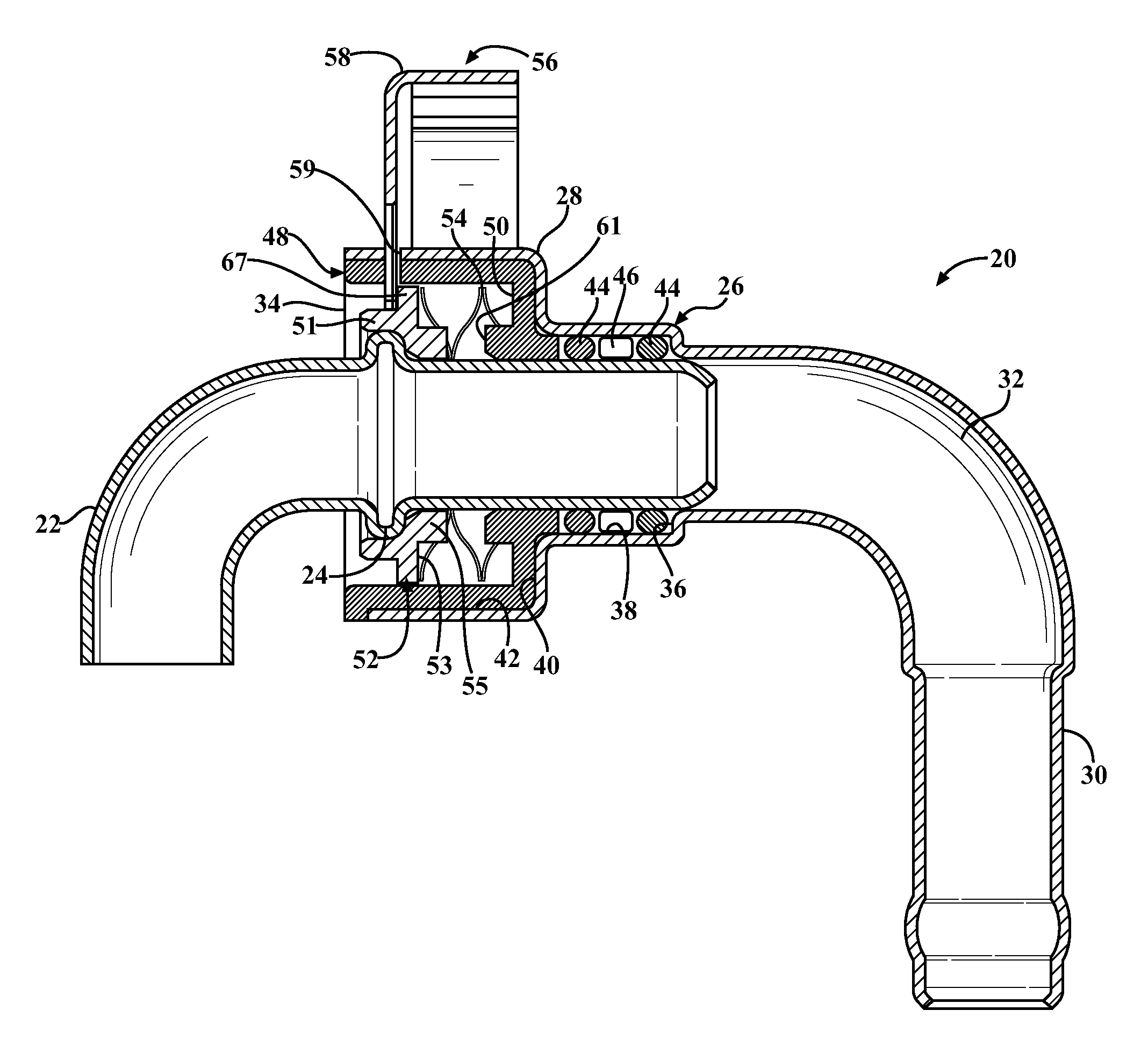
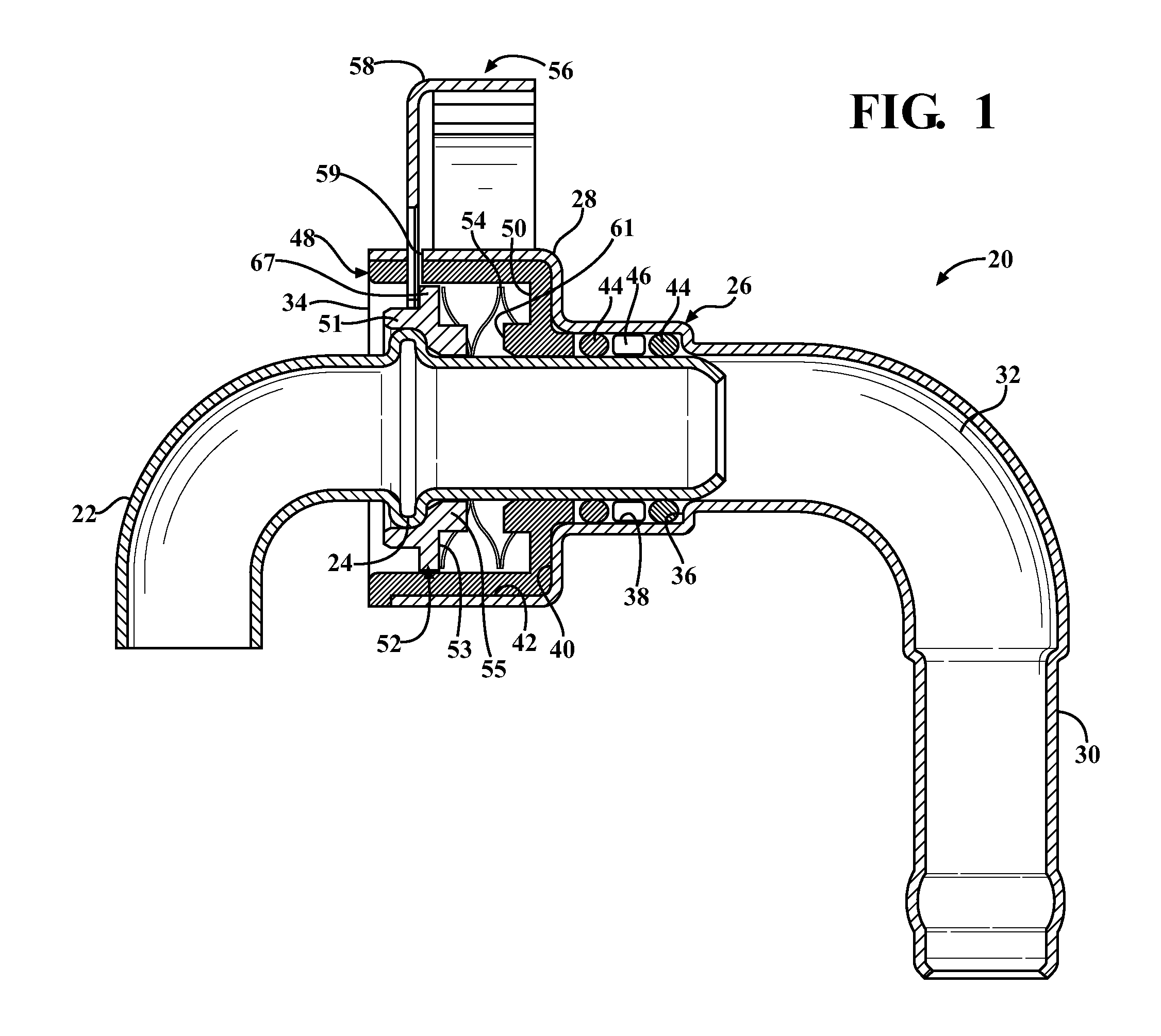
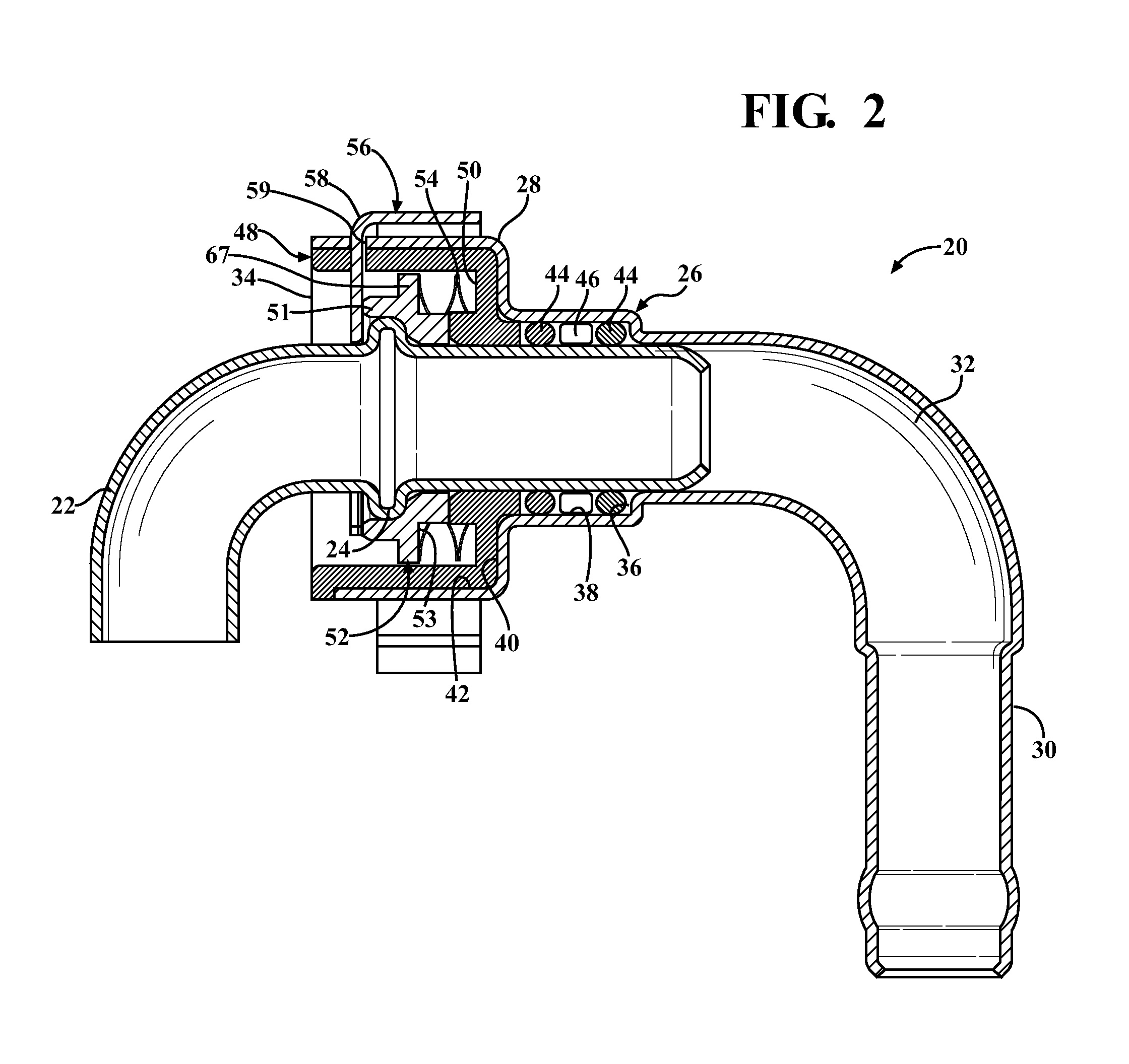
[0017]Referring to the Figures, wherein like numerals indicate corresponding parts throughout the several views, a quick connector assembly 20 for establishing fluid communication between a male end form 22 and another hose or tube (not shown) is generally shown in FIGS. 1-4. The male end form 22 is preferably of metal, has a generally tubular shape and extends to a tube end. The male end form 22 also includes a bead 24, or an annular ridge, spaced a predetermined distance from the tube end.

[0018]The quick connector assembly 20 includes a housing 26, generally indicated, presenting a female receiving portion 28 for receiving the male end form 22 and a stem portion 30 for receiving and establishing fluid communication with a hose or any other tube (not shown). In the exemplary embodiment, the housing 26 is formed of metal which is shaped through a deep drawing process. However, it should be appreciated that any other formable material may be used in place of metal (including, for exa...


PUM


Abstract

A quick connector assembly for quickly connecting and establishing fluid communication between a male end form having a bead and a hose or any other type of tube. The quick connector assembly includes a housing having a stem portion for receiving the hose and a female receiving portion for receiving the male end form. A plunger is disposed within the housing, and the plunger is biased in a first direction by a spring. The quick connector further includes a locker which is held in a non-engaged position until the male end form has been inserted into the housing until the bead moves the plunger in a second direction opposite of the first direction. Once the bead of the male end form clears the locker, the locker can be moved into an engaged position with the bead of the male end form being trapped between the locker and the plunger.

Description

CROSS-REFERENCE TO PRIOR APPLICATION[0001]This PCT patent application claims the benefit of U.S. Provisional Patent Application Ser. No. 61 / 442,057 filed Feb. 11, 2011, entitled “Quick Connector,” the entire disclosure of the application being considered part of the disclosure of this application and hereby incorporated by reference.BACKGROUND OF THE INVENTION[0002]1. Field of the Invention[0003]The present invention relates to quick connector assemblies, and more specifically, to quick connector assemblies which receive and lock with a male end form.[0004]2. Description of the Prior Art[0005]Quick connector assemblies are used in many different applications for quickly connecting and establishing fluid communication between a male end form and a hose or another tube. It is important that the male end form can quickly engage with the quick connector assembly to minimize assembly time and labor, e.g. on an assembly line. At the same time, the quick connector assembly must be very rel...

Claims


Application Information

Patent Timeline
Patent Type & Authority Applications(United States)
IPC IPC(8): F16L37/02
CPCF16L37/02F16L37/144F16L2201/10
Inventor PARKS, BRIANLUTZKE, MATTHEW
Owner A RAYMOND & CO
Learn More