
Abrasive air blast system with air cooler for blast nozzle and air dryer for storage tank

a technology of air cooler and air blast system, which is applied in the direction of grinding/polishing apparatus, grinding machine components, manufacturing tools, etc., can solve the problems of clumping of granular abrasives inside the air blast system and inconsistent surface finish, so as to reduce the cost of installation and maintenance, increase system efficiency, and eliminate the effect of loss of functionality

Active Publication Date: 2012-01-10
AXXIOM MANUFACTUING
View PDF4 Cites 1 Cited by
  • Summary
  • Abstract
  • Description
  • Claims
  • Application Information

AI Technical Summary

Benefits of technology

[0015]In the subject invention all of the compressed air is cooled in a manner sufficient to satisfy the requirements for the pressurized air flowing through the nozzle. Only the small percentage of air that flows into the hopper or vessel is dried. This provides a higher level of dry air flowing into the vessel and insures proper abrasive flow. The system of the subject invention provides optimum air conditioning while at the same time significantly reducing the costs associated with drying the air for the vessel.
[0016]In a system utilizing an active drier such as, by way of example, a deliquescent bed, the consumption of the deliquescent medium is approximately 1% of that used in prior art systems with no loss in functionality. Specifically, by drying the air where it is most needed and more importantly, by not drying the air where it is not needed, substantial increase in system efficiency is achieved. Further, since the compressed air treatment system of the subject invention is drying a much lower volume flow rate, the size of the drying capacity is reduced proportionately. These advantages should equate to lower operating cost and lower equipment cost of the airblast system.
[0018]The resulting airblast system provides a flow through the blast nozzle which is consistent with prior art systems while greatly reducing the costs associated with drying the compressed air which is introduced into the vessel for assuring continuous flow of abrasive through the abrasive metering valve.

Problems solved by technology

Moisture in the compressed, pressurized air causes the granular abrasive inside the airblast system to “clump” and not flow or not flow consistently.
If the “clumping” is excessive the granular abrasive will not gravity flow from the hopper into the mixing chamber and will result in an intermittent flow, causing an inconsistent surface finish.
Second, the compressed air flows through a coalescing pad that will trap moisture droplets.

Method used


Image

  • Abrasive air blast system with air cooler for blast nozzle and air dryer for storage tank
  • Abrasive air blast system with air cooler for blast nozzle and air dryer for storage tank
  • Abrasive air blast system with air cooler for blast nozzle and air dryer for storage tank

Examples


Embodiment Construction

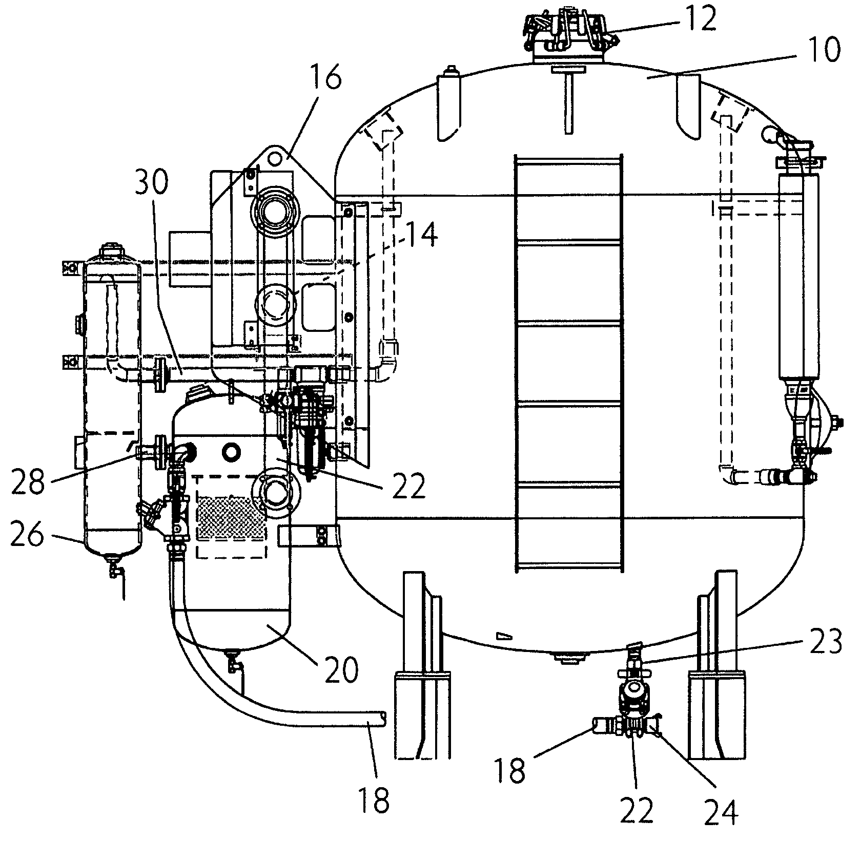
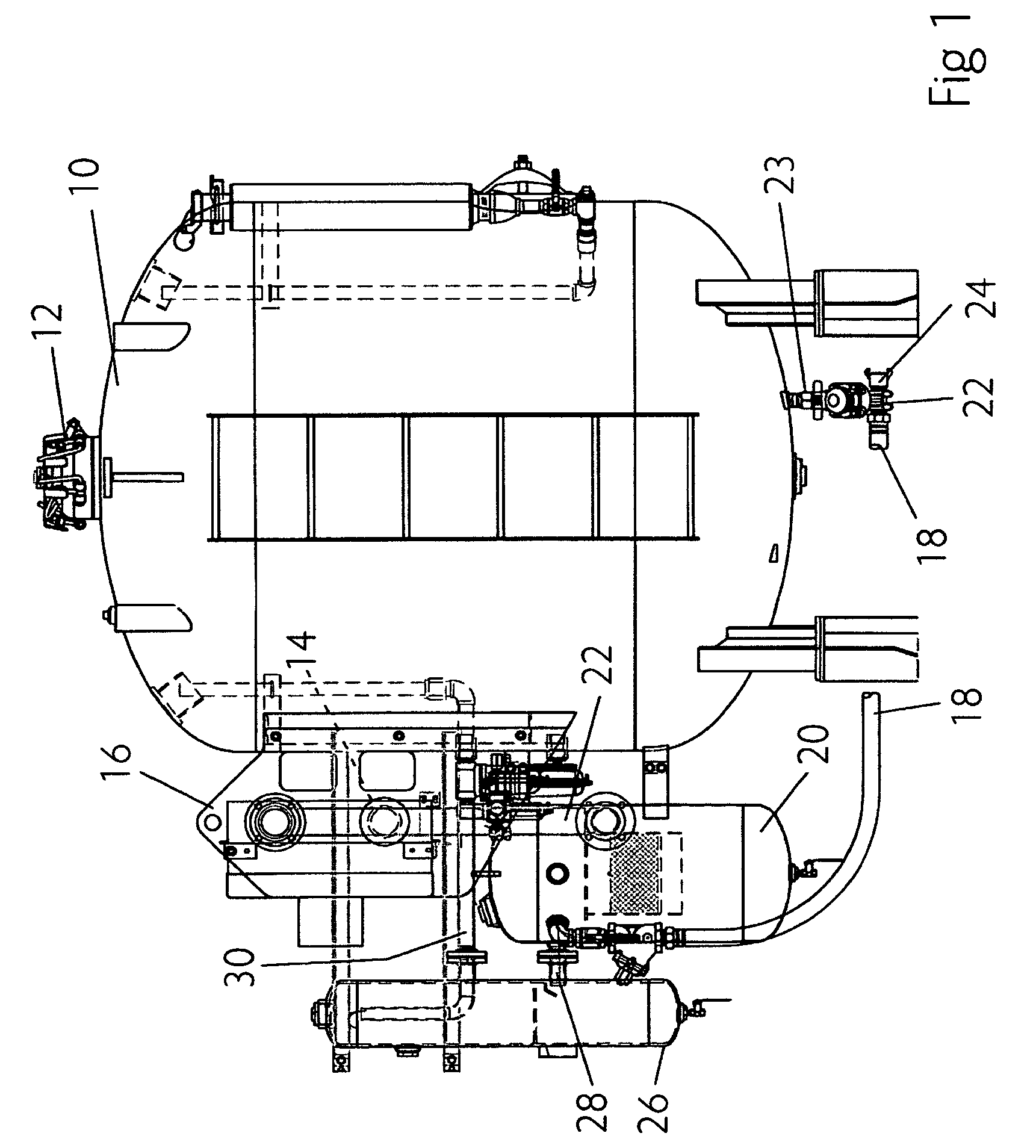
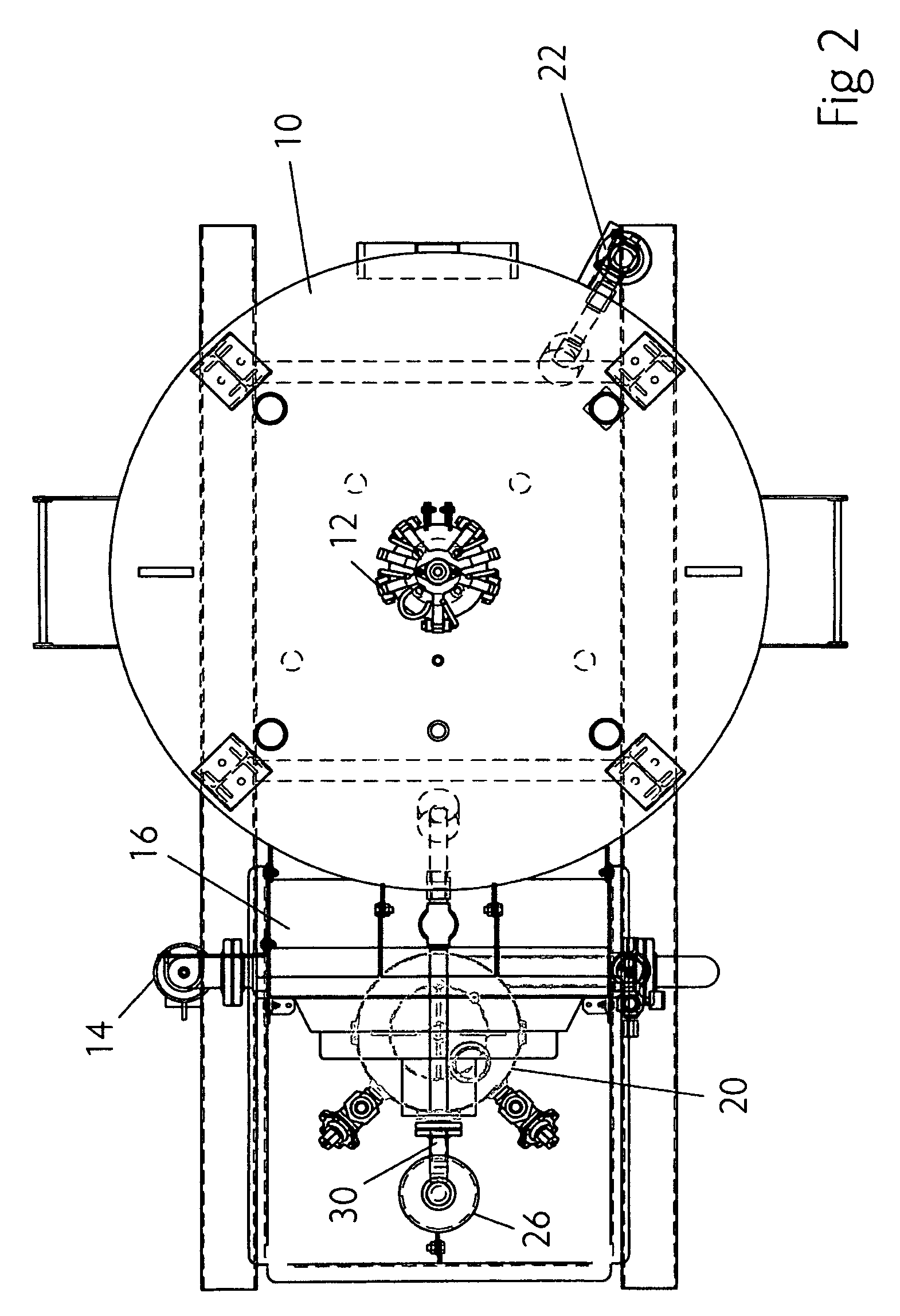
[0023]As shown in FIGS. 1 and 2, a typical airblast system includes a hopper or vessel 10 for housing the granular abrasive media which is introduced through the hatch 12 provided in the top of the vessel. Pressurized air is provided from an external source (not shown) at port 14. The pressurized air is cooled, typically by a radiator-type cooling system 16.

[0024]In a typical system, the pressurized air is cooled to approximately 95° F., or to within about 20° F. of ambient temperature to assure that the dew point is sufficiently lowered to provide uninterrupted flow through the blast line 18. The radiator cooled air flows from the cooling system 16 into an aftercooling vessel 20 via a flow line 22. The cooled air is then released from the aftercooling vessel 20 into a blast line 18 where it is mixed with abrasive media released from the hopper 10 via line 23 at an abrasive metering valve 22. The high flow air and abrasive mixture are then delivered to a blast nozzle (not shown) via...


PUM


Abstract

An abrasive blaster system includes a storage tank for storing dry granular abrasive media, a source of pressurized air and a metering valve for mixing the granular abrasive media with the pressurized air for release through a blast nozzle. A cooling system is in line with the source of pressurized air for cooling the air received from the source before it is introduced to the metering valve, whereby cooled air is introduced into the metering valve. The system also includes a dryer system downstream of the cooling system and adapted for selectively receiving a portion of the cooled air for further drying it. The dryer system is in communication with the storage tank, whereby cooled, dry air is introduced into the storage tank.

Description

BACKGROUND[0001]1. Field of the Invention[0002]The invention is generally related to abrasive airblast systems and is specifically directed to air drying and treatment means for such systems.[0003]2. Discussion of the Prior Art[0004]Abrasive blasting is a well known operation for cleaning or preparing a surface by forcibly propelling a stream of abrasive material against it. Abrasive blasting systems have been around for over a century, with an early blasting processed patented by Benjamin Chew Tilghman on Oct. 18, 1870. In such operations the abrasive material is made up of small granular or particulate matter which is introduced into a pressurized air stream for dry blasting or a fluid for wet blasting.[0005]Dry abrasive blasting applications are typically powered from an air compressor and are known as airblast systems. Most applications involve a pressurized vessel that contains the abrasive and meters it into the compressed air stream, primarily by gravity flow.[0006]Typical pr...

Claims


Application Information

Patent Timeline
Patent Type & Authority Patents(United States)
IPC IPC(8): B24C7/00
CPCB24C7/0046
Inventor NGUYEN, PHUONG TAYLOR
Owner AXXIOM MANUFACTUING
Learn More