
Battery simulation circuit

a battery simulation and circuit technology, applied in electrical testing, measurement devices, instruments, etc., can solve problems such as reducing the battery life of electronic devices

Active Publication Date: 2013-11-21
FU TAI HUA IND SHENZHEN +1
View PDF2 Cites 6 Cited by
  • Summary
  • Abstract
  • Description
  • Claims
  • Application Information

AI Technical Summary

Benefits of technology

The patent text talks about a device that uses a lithium-ion battery as a power source. The device needs to be tested to check its various functions. However, the testing process can drain the battery life. So, the technical effect of the patent is to find a way to quickly test the device without reducing the battery life.

Problems solved by technology

However, the functions test takes long time, thus it could reduce the battery life of the battery in the electronic device.

Method used


Image

  • Battery simulation circuit
  • Battery simulation circuit
  • Battery simulation circuit

Examples


Embodiment Construction

[0009]Reference will be made to the drawings to describe various embodiments.

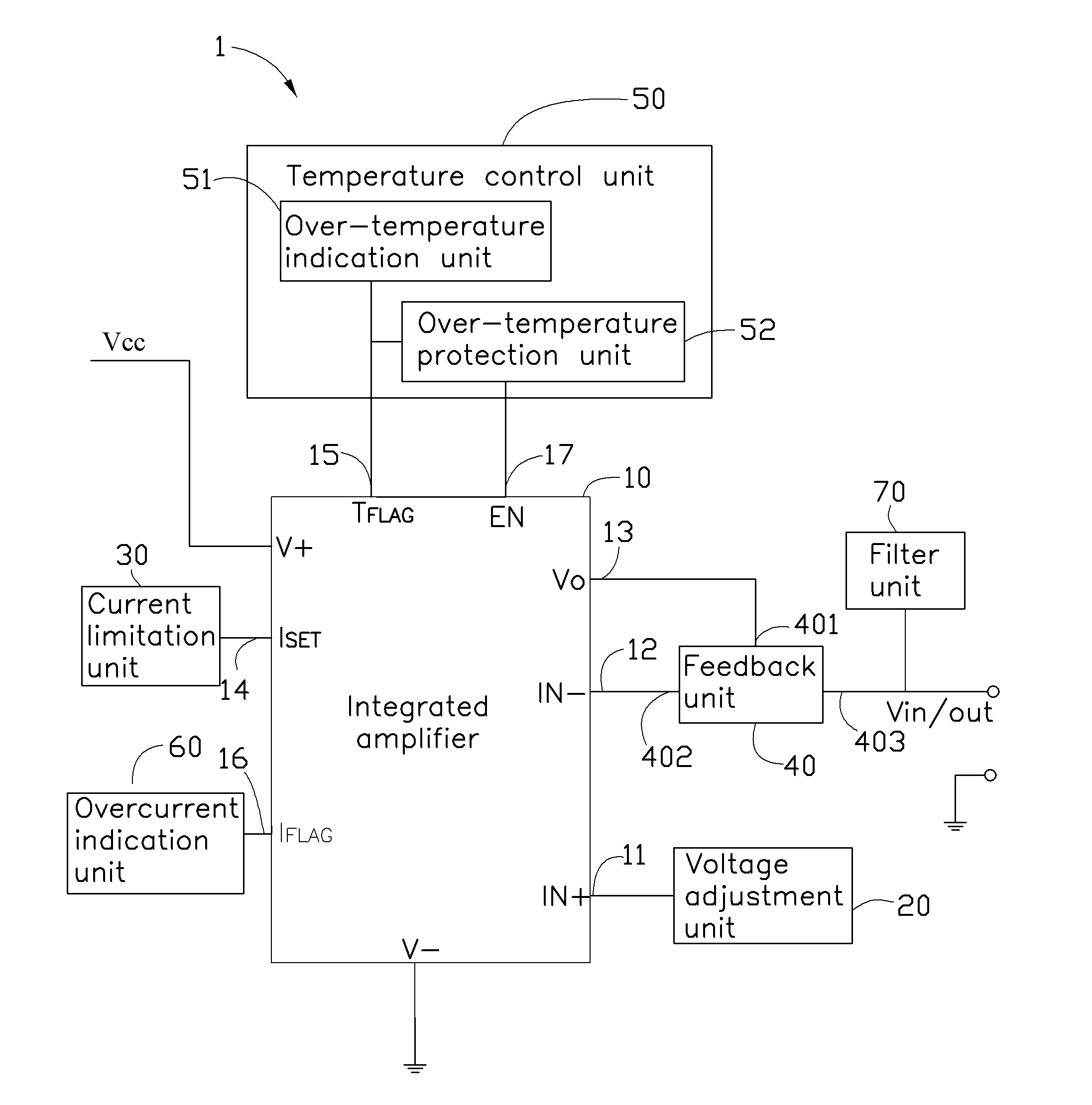
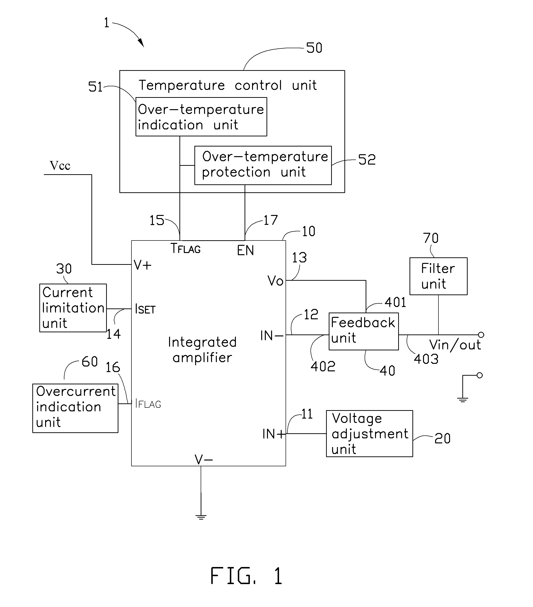
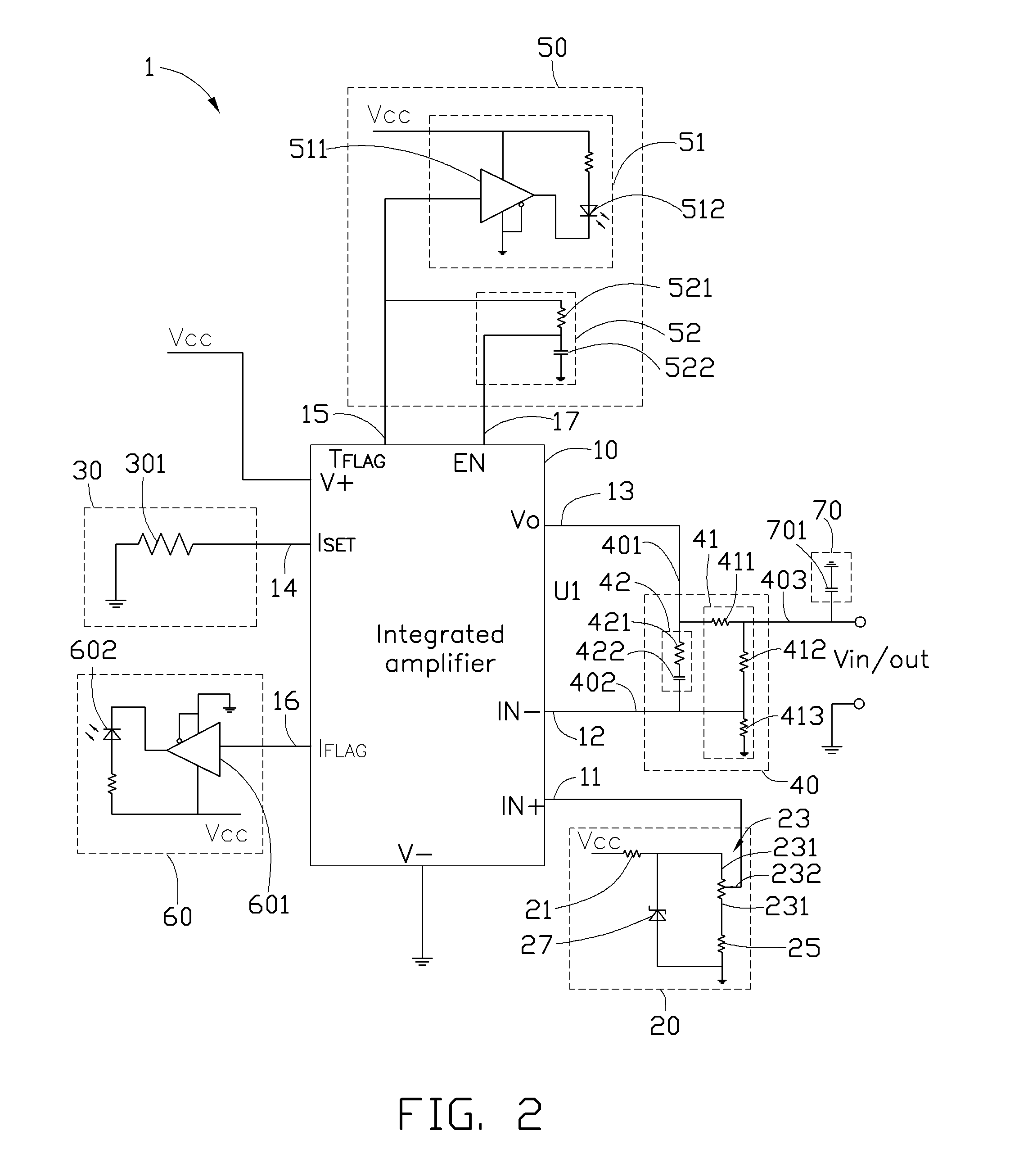
[0010]FIG. 1 is a block diagram of a battery simulation circuit 1 according to an exemplary embodiment of the present disclosure. The battery simulation circuit 1 simulates a battery supplying power for an electronic device, and can also simulate a rechargeable battery when testing the ability of the electronic device to recharge a battery. The battery simulation circuit 1 includes an input / output terminal Vin / out to connect to the electronic device, and further includes an integrated amplifier 10, a voltage adjustment unit 20, a current limitation unit 30, a feedback unit 40, a temperature control unit 50, and an overcurrent indication unit 60. Preferably, the battery simulation circuit 1 further includes a filter unit 70 to filter a signal via the input / output terminal Vin / out. In the embodiment, the integrated amplifier 10 is an OPA567 made by TI.

[0011]The voltage adjustment unit 20 provides a reference ...


PUM


Abstract

A battery simulation circuit simulates a rechargeable battery. The battery simulation circuit includes an integrated amplifier, a voltage adjustment unit, a current limitation unit, and a feedback unit. The voltage adjustment unit provides a reference voltage for the integrated amplifier; the current limitation unit provides a reference current for the integrated amplifier and the feedback unit provides a negative feedback signal for the integrated amplifier to control the integrated amplifier working in a linear state. The integrated amplifier outputs an output signal according to the reference voltage and the reference current; the battery simulation circuit supplies power for an electronic device. When the output terminal is connected to a DC power source and a voltage of the DC power source is greater than the output voltage of the output terminal, the battery simulation circuit simulates a battery being recharged by the DC power source via the output terminal.

Description

BACKGROUND[0001]1. Technical Field[0002]The present disclosure relates to a battery simulation circuit, and particularly to a circuit simulating a rechargeable battery.[0003]2. Description of Related Art[0004]An electronic device may include a lithium-ion battery as a power source. A manufacturing company needs to test a plurality of functions of the electronic device. However, the functions test takes long time, thus it could reduce the battery life of the battery in the electronic device.[0005]Therefore, what is needed is a means to overcome the above described shortcoming.BRIEF DESCRIPTION OF THE DRAWINGS[0006]The components in the drawings are not necessarily drawn to scale, the emphasis instead being placed upon clearly illustrating the principles of at least one embodiment. In the drawings, like reference numerals designate corresponding parts throughout the various views.[0007]FIG. 1 is a block diagram of a battery simulation circuit according to an exemplary embodiment of th...

Claims


Application Information

Patent Timeline
Patent Type & Authority Applications(United States)
IPC IPC(8): G01R31/00
CPCG01R31/00G01R31/2848
Inventor YU, QI-LONGCHUANG, TSUNG-JENZHANG, JUNWONG, SHIH-FANGZHANG, JUN-WEIZHOU, JIAN-JUN
Owner FU TAI HUA IND SHENZHEN
Learn More