Touchscreen with analog pressure detection as user interface for industrial technical device

a technology of industrial technology and user interface, applied in the direction of programming, instruments, computing, etc., can solve the problems of not allowing an ergonomically sensible operating sequence and the inability to operate the same way

Inactive Publication Date: 2013-11-21
SIEMENS AG
View PDF8 Cites 19 Cited by
  • Summary
  • Abstract
  • Description
  • Claims
  • Application Information

AI Technical Summary

Benefits of technology

[0026]Advantageously, the touchscreen may be disposed on an upper side of the operator interface. The operator interface may advantageously have a handle disposed, for example, on the underside. The operator can then hold the operator interface in a comfortable and simple manner.

Problems solved by technology

In the prior art two actions are thus generally required which, especially during operation with a mobile panel, does not allow an ergonomically sensible operating sequence.
This method of operation too is not ergonomically viable.

Method used


Image

  • Touchscreen with analog pressure detection as user interface for industrial technical device
  • Touchscreen with analog pressure detection as user interface for industrial technical device
  • Touchscreen with analog pressure detection as user interface for industrial technical device

Examples


Embodiment Construction

[0042]Throughout all the figures, same or corresponding elements may generally be indicated by same reference numerals. These depicted embodiments are to be understood as illustrative of the invention and not as limiting in any way. It should also be understood that the figures are not necessarily to scale and that the embodiments are sometimes illustrated by graphic symbols, phantom lines, diagrammatic representations and fragmentary views. In certain instances, details which are not necessary for an understanding of the present invention or which render other details difficult to perceive may have been omitted.

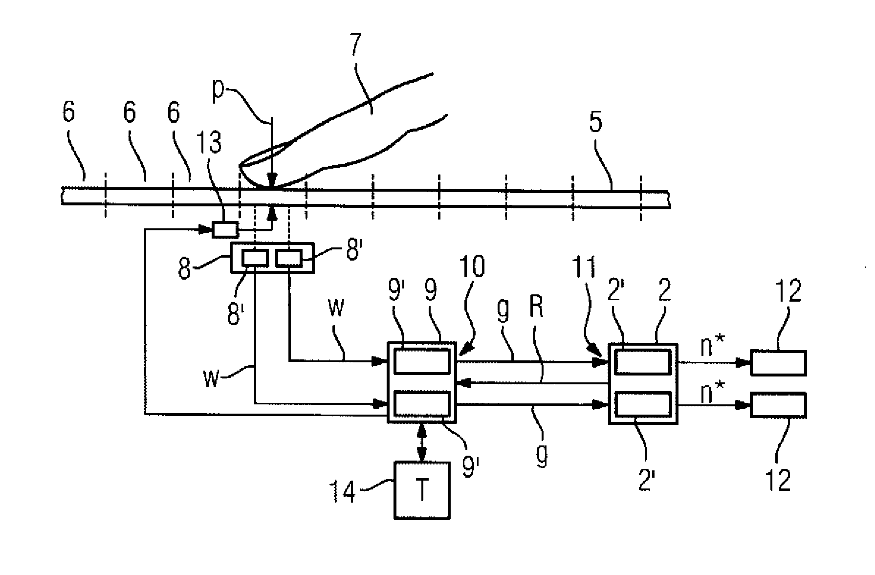
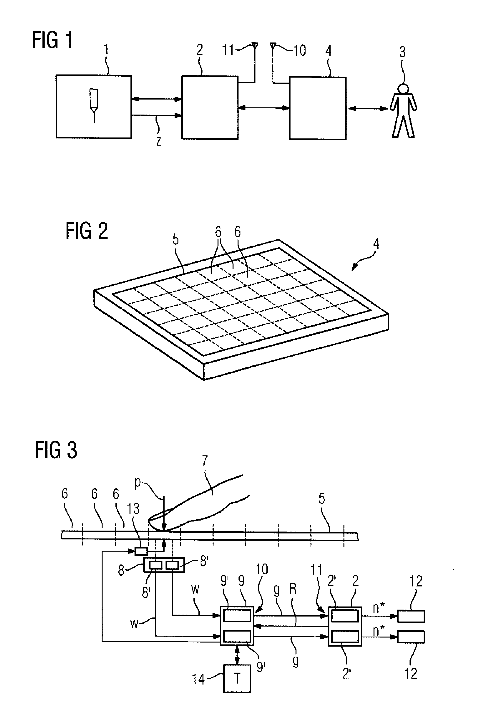
[0043]Turning now to the drawing, and in particular to FIG. 1, there is shown an industrial technical device 1—in the illustrated embodiment a drilling machine—which is controlled by a control device 2. The control device 2 accepts inputs from an operator 3 of the industrial technical device 1 via an operator interface 4, which he intends to enter as part of the control of t...


PUM


Abstract

Pressure is applied to an area of a touchscreen by an operator of an industrial technical device. A value dependent on the applied pressure is generated by a sensor device associated with the area and supplied to an evaluation device. In a normal operating mode, a variable dependent on the applied pressure is transmitted by the evaluation device to a control device. The control device activates an element of the industrial technical device and outputs to the element a setpoint value dependent on the applied pressure, when the pressure defined by the transmitted variable exceeds a first threshold value. The setpoint value is a monotonously increasing function of the pressure and has the value zero until the pressure exceeds a second threshold value greater than the first threshold value.

Description

CROSS-REFERENCES TO RELATED APPLICATIONS[0001]This application claims the priority of European Patent Application, EP 12 168 253, filed May 16, 2012, pursuant to 35 U.S.C. 119(a)(d), the content of which is incorporated herein by reference in its entirety as if fully set forth herein.BACKGROUND OF THE INVENTION[0002]The present invention relates to a method for operating an industrial technical device and to an industrial technical device.[0003]The following discussion of related art is provided to assist the reader in understanding the advantages of the invention, and is not to be construed as an admission that this related art is prior art to this invention.[0004]Conventional hard-keys and soft-keys are generally used on operating panels, mobile operating panels and machine control panels for operation of machines. Only one function is ever assigned to such keys, which is activated by pressing the corresponding key and deactivated by releasing the corresponding key. With hard-keys...

Claims


Application Information

Patent Timeline
Patent Type & Authority Applications(United States)
IPC IPC(8): G06F3/041
CPCG06F3/0414G05B19/0423G06F3/04144
Inventor HAUF, RONALD
Owner SIEMENS AG
Why Eureka
Try Eureka