Charging apparatus

Active Publication Date: 2013-11-21
SHINDENGEN ELECTRIC MFG CO LTD
View PDF2 Cites 8 Cited by
  • Summary
  • Abstract
  • Description
  • Claims
  • Application Information

AI Technical Summary

Benefits of technology

[0020]According to claim 1 of the present invention, when the power supply plug is inserted into the case, and the engaging part of the power supply plug is engaged with the engaging part of the case, the periphery of the slidable pin abuts against the periphery of the slidable pin to lock the power supply plug and the case. Therefore, any bending stress is not applied to the slidable pin unlike the configuration in which the slidable pin slides in the direction perpendicular to the engaging part of the power supply plug and is fixed, so that the reliability of the locking device is not adversely affected. Furthermore, the case serves not only as means of protection against rain but also as means of supporting the connector socket and the locking device, so that an increase in size and design complexity of the charger main unit can be avoided.
[0021]According to claim 2 of the present invention, since the slidable pin is disposed at a position where the slidable pin faces in the opposite direction to the direction of insertion of the swing pin, a configuration can be easily provided in which the swing pin pushes the slidable pin when the power supply plug is inserted into the case, and the slidable pin is restored to its original position so that the periphery of the swing pin abuts against the periphery of the slidable pin when the engagi

Problems solved by technology

However, the manipulation part and the display part also have to be provided in the forward part of the main unit of the charging apparatus, so that the charger main unit becomes larger and more complicated in design.
In addition, in the case when the charging apparatus is installed outdoors, there is a possibility that the solenoid gets wet with rain entering from the

Method used


Image

  • Charging apparatus
  • Charging apparatus
  • Charging apparatus

Examples


Example

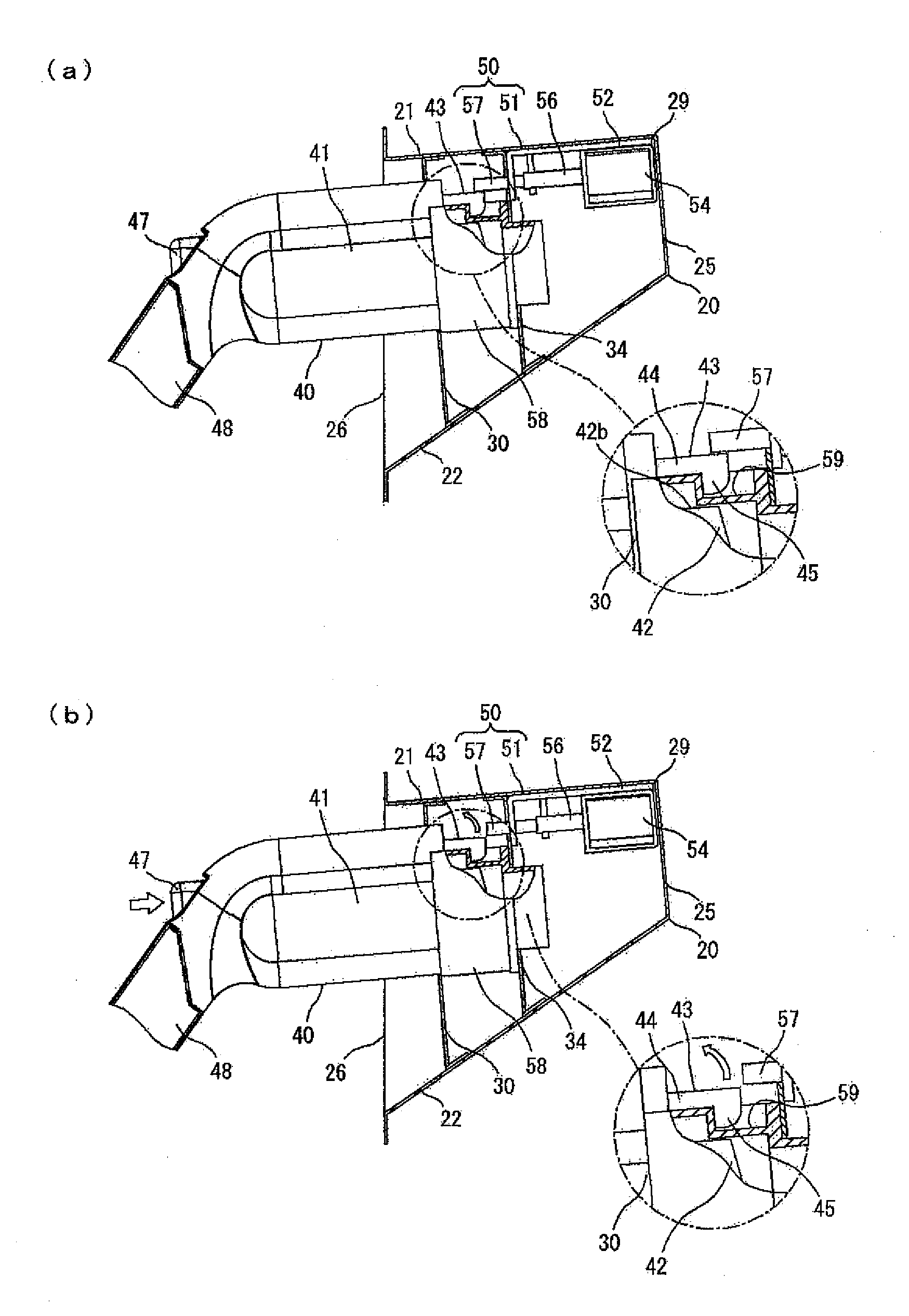
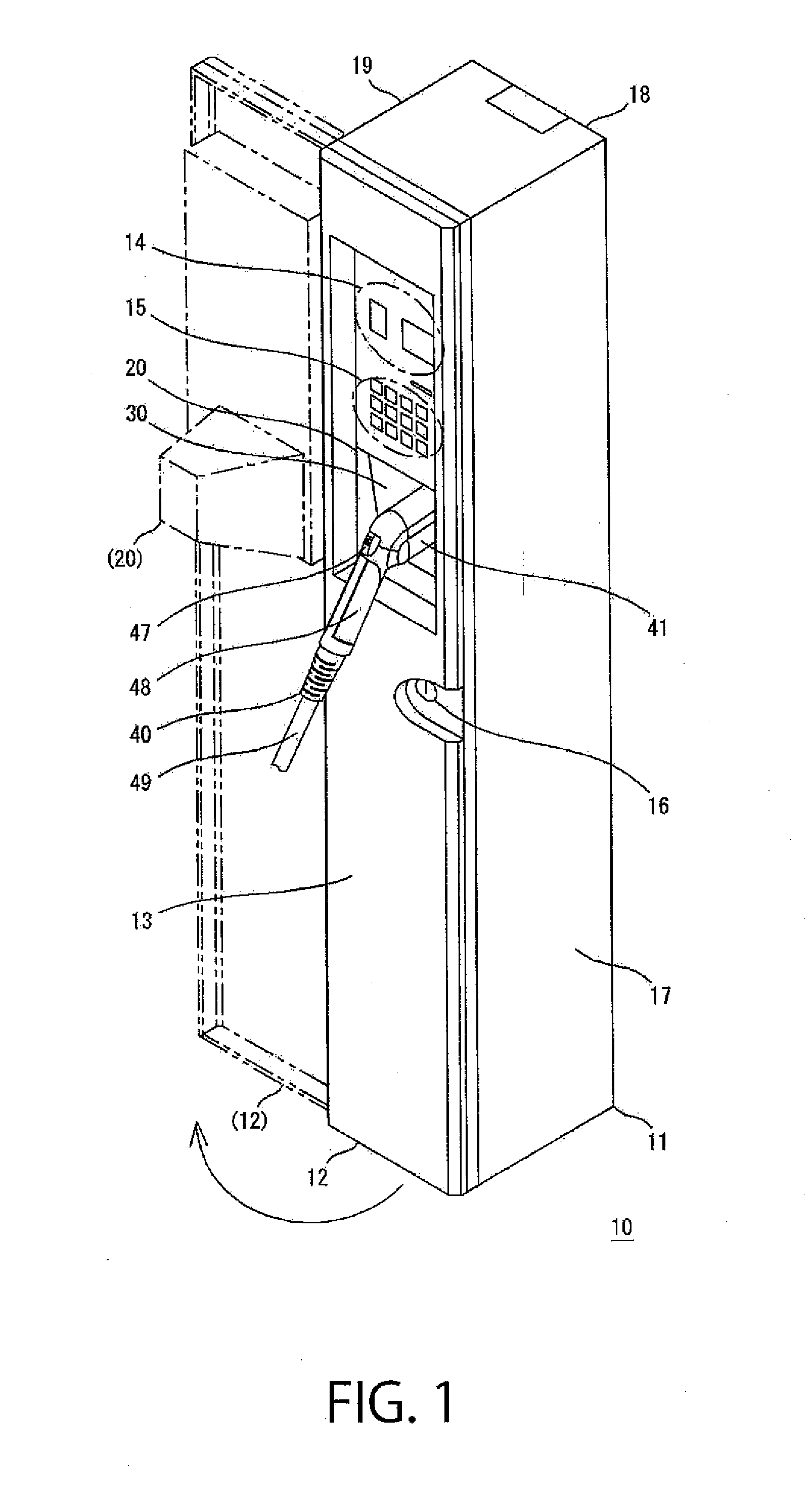
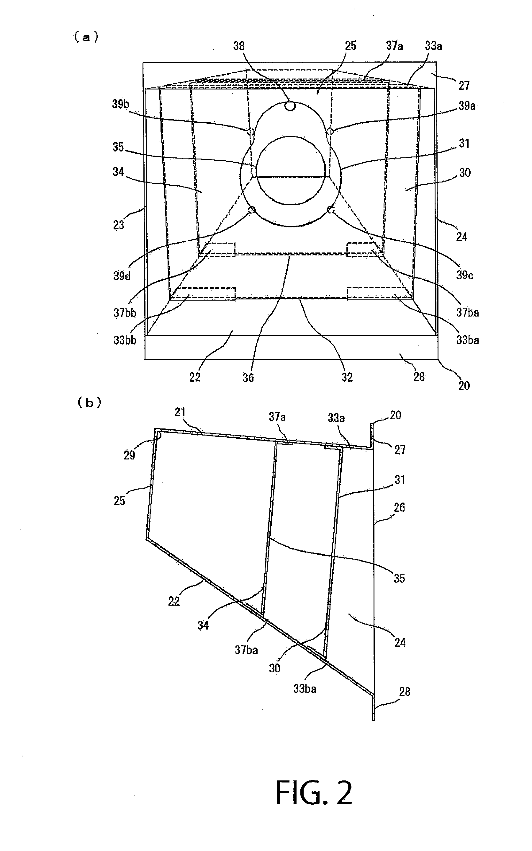
[0043]In the following, a charging apparatus according to an embodiment of the present invention will be described with reference to the drawings. Although the following description will be made on the assumption that the charging apparatus according to this embodiment is installed at a charging station or outdoor parking lot where the charging apparatus is exposed to rain and wind, the charging apparatus according to the present invention can also be installed at an underground parking lot or in a multistory parking space, for example. In other words, the installation site of the charging apparatus is not limited to places where the charging apparatus is exposed to rain and wind. The charging apparatus according to the present invention can be used not only for charging of electric automobiles or electric motorcycles but also for various other mobile equipment, such as construction equipment, provided with a battery. In the drawings, illustration of some screws or screw holes is om...


PUM


Abstract

When a power supply plug 40 is inserted into a case 20, a swing pin 43 of the power supply plug 40 pushes a slidable pin 57 in the case 20. Then, when an engaging part 45 of the power supply plug 40 provided at the tip end of the swing pin 43 is engaged with an engaging part 59, the slidable pin 57 is restored to its original position at a mouth, and the periphery of the swing pin 43 abuts against the periphery of the slidable pin 57, and thus the power supply plug 40 and the case 20 are locked. In addition, a locking device 50 having the slidable pin is disposed at the back of the case 20, and a first waterproof wall 30 and a second waterproof wall 34 are provided at positions closer to the mouth than the locking device 50.

Description

TECHNICAL FIELD[0001]The present invention generally relates to a charging apparatus. In particular, it relates to a charging apparatus with a power supply plug that can be locked to prevent tampering or damage to the power supply plug.BACKGROUND ART[0002]Some charging apparatuses serving as a charger that supplies power to a battery of an electric automobile or an electric motorcycle have: a lock mechanism provided in the housing of the charger main unit that permits the user to pull the power supply plug out of the housing of the charging apparatus only after the user performs an unlocking operation, in order to avoid an accident caused by tampering by a child or an accident caused by damage to the power supply plug. Such charging apparatuses have to be configured to allow an appropriate user to easily attach and detach the power supply plug and to reliably inhibit an inappropriate user from pulling out the power supply plug.[0003]In the following, an example of a charging apparat...

Claims


Application Information

Patent Timeline
IPC IPC(8): H01R13/639
CPCH01R13/639H01R13/6275B60L3/0069B60L2200/12B60L2270/32B60L2270/34Y02T90/14B60L53/16B60L53/305Y02T10/7072Y02T10/70Y02T90/12Y02T90/16H02J7/00E05B65/00H01R13/73
Inventor MIZUNO, MASAHIDEKAWAHARA, MASANORIAOKI, YOSHIO
Owner SHINDENGEN ELECTRIC MFG CO LTD
Why Eureka
Try Eureka