
Wireless network of environmental sensor units

a sensor unit and wireless network technology, applied in the direction of wireless network protocols, instruments, digital computers, etc., can solve the problems of large monetary loss, serious business disruption, food product damage,

Active Publication Date: 2013-11-21
DIGI INTERNATIONAL
View PDF27 Cites 89 Cited by
  • Summary
  • Abstract
  • Description
  • Claims
  • Application Information

AI Technical Summary

Benefits of technology

The invention provides a system for monitoring environmental conditions in an environment. It includes an environmental sensor unit and a base station that automatically connect with each other when powered. The system also includes a server to analyze and store the data collected by the sensor unit. The base station can communicate with the server using a wireless communication protocol. The invention enables seamless monitoring of environmental conditions and provides access to a variety of networks. It allows for efficient data transmission and analysis, improving the accuracy and reliability of environmental monitoring.

Problems solved by technology

If a malfunction of the refrigeration equipment is not detected promptly, food could become too hot or too cold, resulting in damage to the food products.
For a business that relies on food, such damage could result in a large monetary loss and potentially a serious business disruption.
Sometimes, a malfunctioning component of the computer equipment will generate excessive heat, or a cooling system for reducing a temperature of the computer equipment may malfunction or fail, resulting in a temperature of the computer equipment increasing.
Excessive heat may cause components to fail because they are operating beyond their proper operating temperature.
An increase in temperature of the computer equipment may therefore indicate a defect that may need to be corrected before such a failure.

Method used


Image

  • Wireless network of environmental sensor units
  • Wireless network of environmental sensor units
  • Wireless network of environmental sensor units

Examples


Embodiment Construction

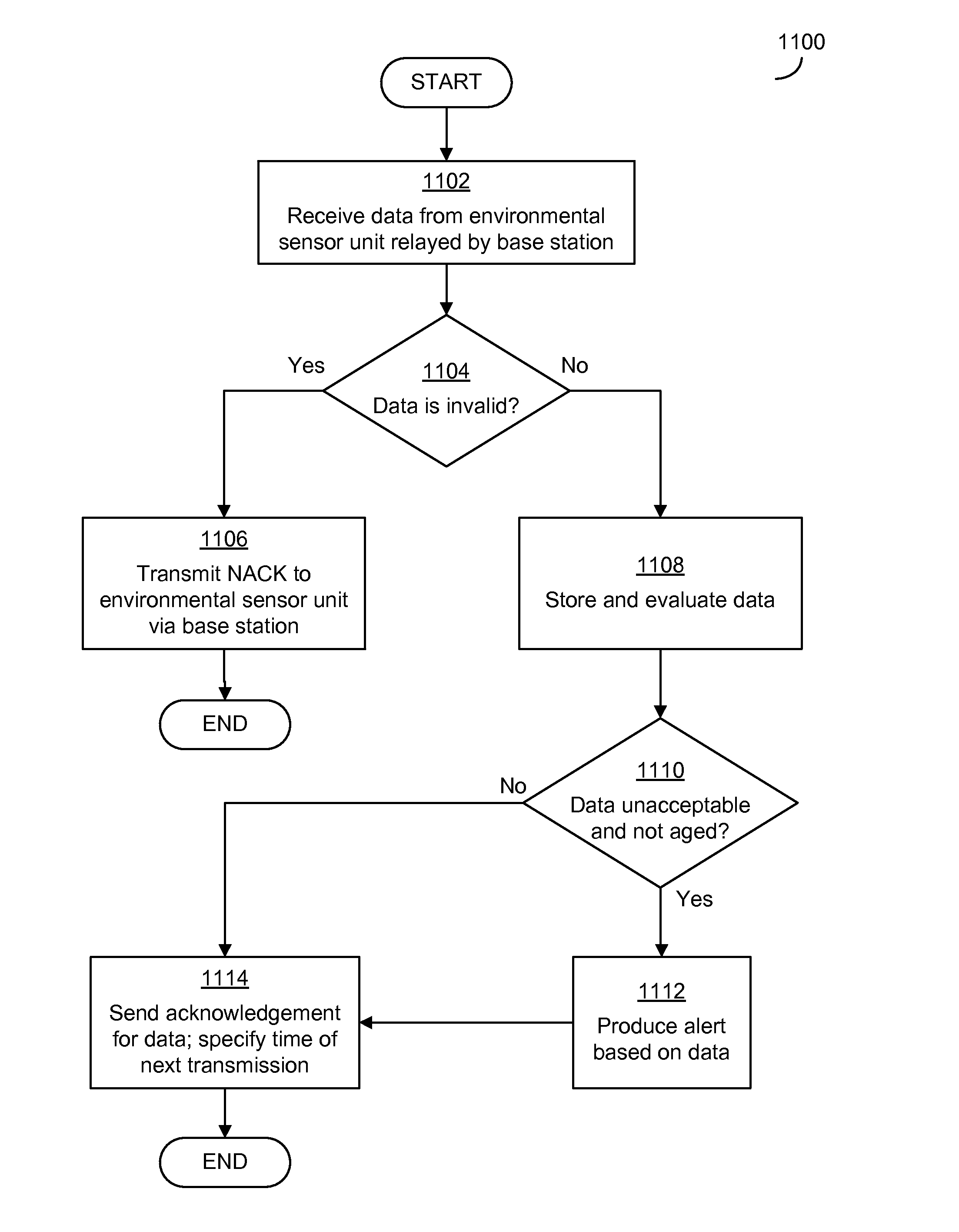
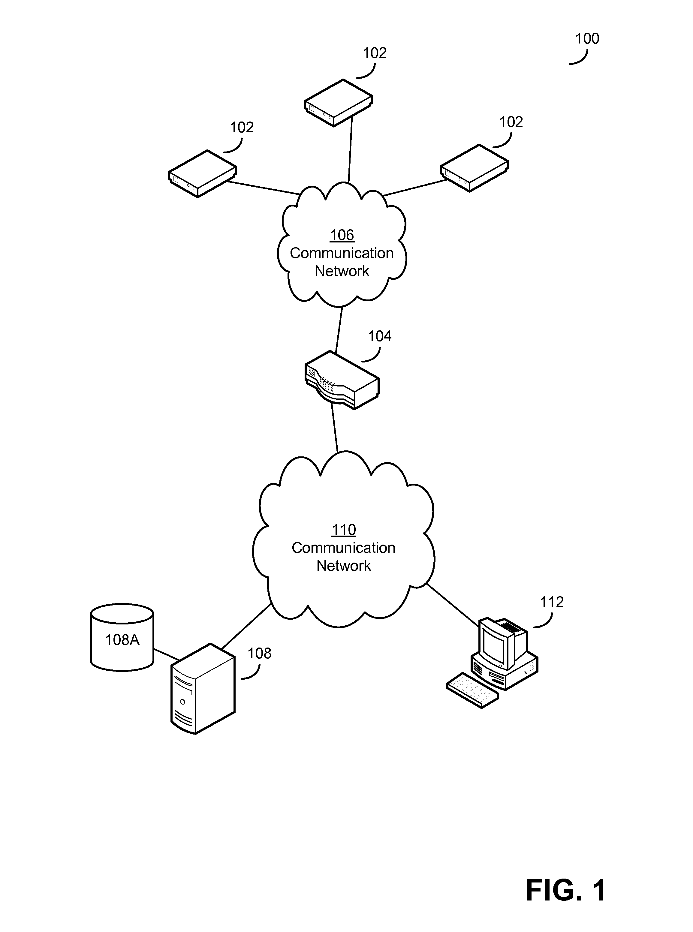
[0026]Applicant has recognized and appreciated that difficulty in setting up and configuring an environmental monitoring system adds to the cost and impedes the use of environmental monitoring. As a result, environmental monitoring is not currently used in all scenarios in which it could prevent waste or other problems that might be prevented by detecting undesired environmental conditions. Further, the Applicant has recognized and appreciated that wireless networks including low-power environmental sensor units and base stations that communicate with a server regarding environmental conditions of the environmental networks can provide simple installation of an environmental monitoring system, even when the area to be monitored is relatively large. These units may be designed to operate together, without express programming or other express configuration.

[0027]In some embodiments, the base station may be configured to communicate with a server that monitors environmental conditions ...


PUM


Abstract

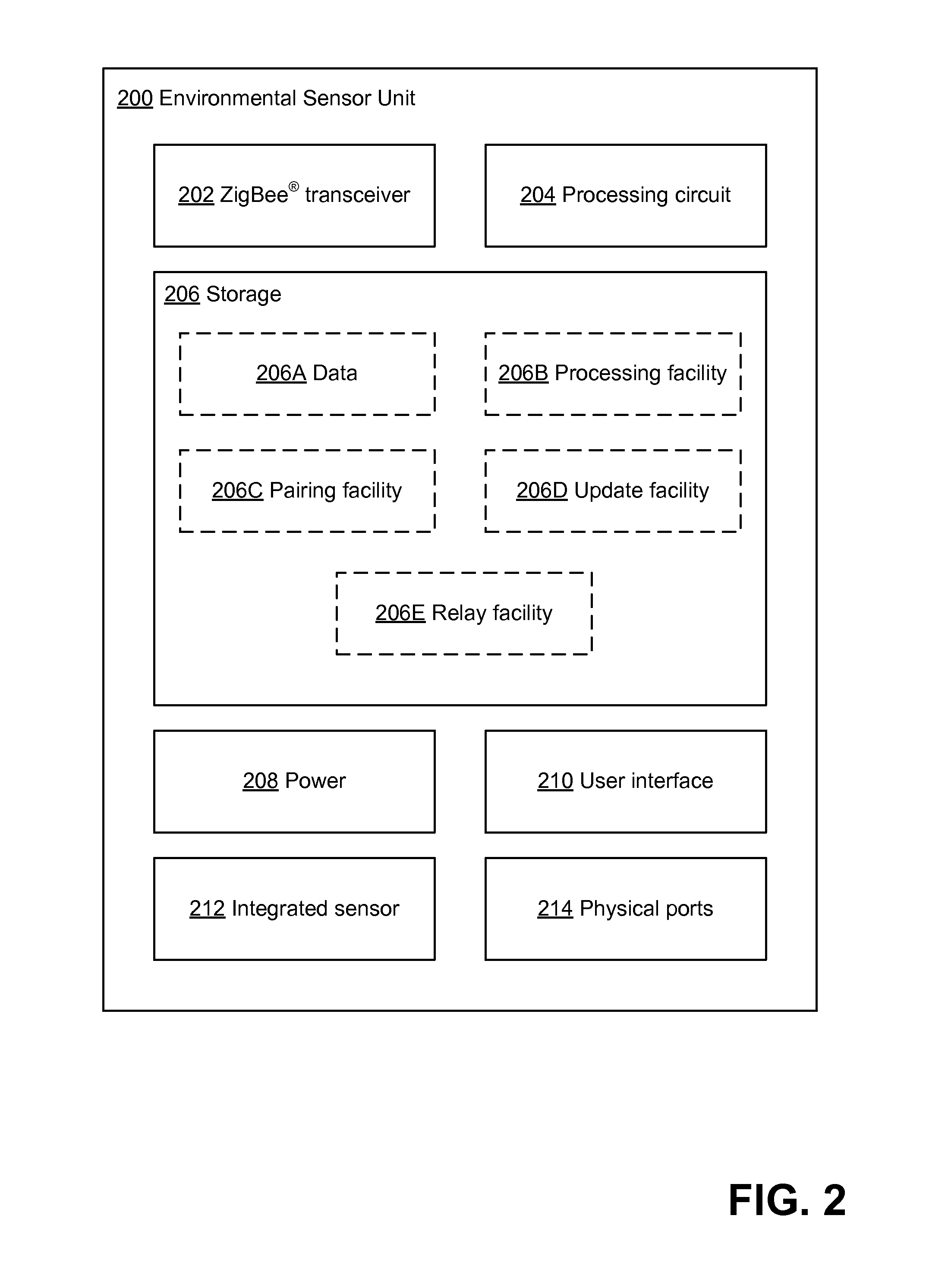
Environmental monitoring systems that include base stations and environmental sensor units (ESUs) that communicate in a wireless sensor network. A base station may include environmental sensors and may communicate with a remote server using a wide-area wireless network. The base station may also communicate with an environmental sensor unit using a wireless personal area network. The ESU may include environmental sensors and may communicate with the remote server via the base station. The base station and ESU may be adapted to automatically pair with one another to enable the ESU to communicate via the base station. An ESU may also be adapted to process data regarding environmental conditions by automatically determining a type of environmental sensor from which the data was received and processing the data based on the type. An ESU may also include physical ports by which new sensors can be connected to the ESU.

Description

BACKGROUND[0001]Temperature monitoring is used in many industries. For example, restaurants and food processing companies that rely on refrigeration equipment to keep their products fresh frequently use temperature monitoring. If a malfunction of the refrigeration equipment is not detected promptly, food could become too hot or too cold, resulting in damage to the food products. For a business that relies on food, such damage could result in a large monetary loss and potentially a serious business disruption.[0002]As another example, companies that operate servers or other computer equipment may also monitor temperature of their equipment. Sometimes, a malfunctioning component of the computer equipment will generate excessive heat, or a cooling system for reducing a temperature of the computer equipment may malfunction or fail, resulting in a temperature of the computer equipment increasing. Excessive heat may cause components to fail because they are operating beyond their proper o...

Claims


Application Information

Patent Timeline
IPC IPC(8): G06F15/00
CPCH04L67/12H04L67/34H04L67/125H04W80/085H04W4/50
Inventor SCHECHTER, HARRY J.
Owner DIGI INTERNATIONAL
Learn More