Method for controlling back clearance of a motion transmission apparatus

a technology for motion transmission apparatus and back clearance, which is applied in the direction of belt/chain/gearing, friction gearing, belt/chain/gearing, etc., can solve the problems of vibration, noise, even damage, and achieve the effect of reducing, generating and even eliminating the back clearance of the motion transmission apparatus

Inactive Publication Date: 2013-11-28
JAN JOHNSON
View PDF3 Cites 8 Cited by
  • Summary
  • Abstract
  • Description
  • Claims
  • Application Information

AI Technical Summary

Benefits of technology

[0008]The primary object of the present invention is to provide a method for controlling back clearance of a motion transmission apparatus, which is capable of controlling the generation, reduction and even elimination of a back clearance of a motion transmission apparatus to meet different needs.

Problems solved by technology

However, there is always back clearance between the electric motor and the toothed elements due to the factors of manufacturing tolerance and abrasion, and the back clearance will cause collision between teeth at the time the electric motor starts, runs or stops, which consequently causes vibration, noise and even damage.

Method used


Image

  • Method for controlling back clearance of a motion transmission apparatus
  • Method for controlling back clearance of a motion transmission apparatus
  • Method for controlling back clearance of a motion transmission apparatus

Examples


Embodiment Construction

[0018]The present invention will be clearer from the following description when viewed together with the accompanying drawings, which show, for purpose of illustrations only, the preferred embodiment in accordance with the present invention.

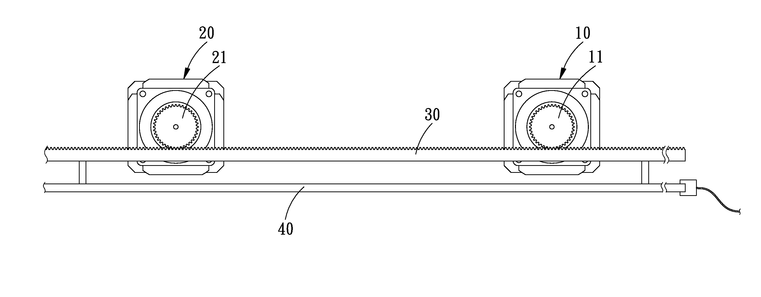
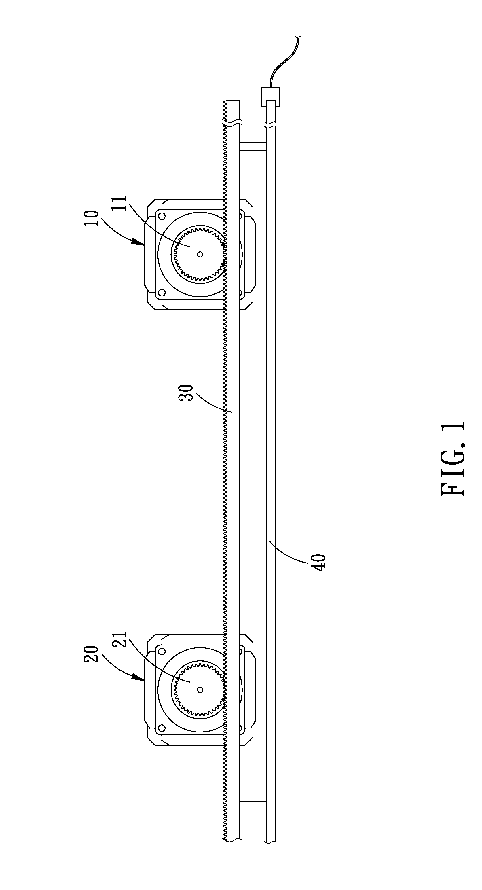
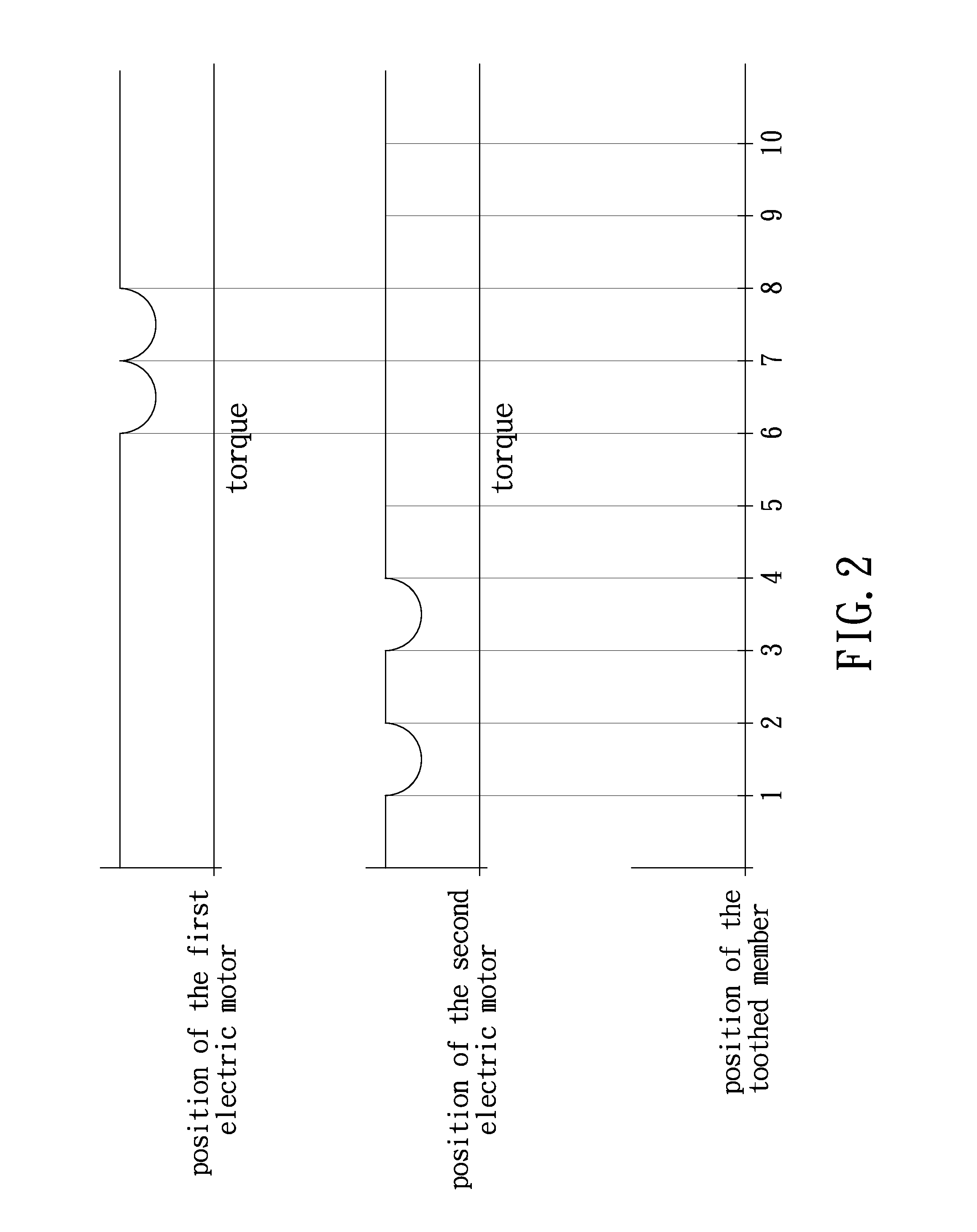
[0019]Referring to FIGS. 1 and 2, the present invention is aimed at providing a method for controlling back clearance of a motion transmission apparatus, wherein the motion transmission apparatus comprises: a first electric motor 10 with a first toothed drive member 11, a second electric motor 20 with a second toothed drive member 21, and a toothed member 30 to be engaged with the first and second toothed drive members 11, 21. The first and second electric motors 10, 20 are servo motors, and the operation and structure of the servo motors are conventional, so no further description is necessary. The first and second toothed drive members 11, 21 are toothed wheels. The toothed member 30 can be toothed bar, worm wheel, screw, and etc. In this embod...


PUM


Abstract

A method for controlling back clearance of a motion transmission apparatus, is capable of controlling the generation, reduction and even elimination of a back clearance of a motion transmission apparatus to meet different needs. The motion transmission apparatus comprises: a first electric motor, a second electric motor, and a toothed member engaged with the first and second toothed drive members, when the toothed member needs to be precisely positioned, the back clearance between the second electric motor and the toothed member at different positions of the toothed member will be controlled according to the torque change, so as to consequently change a position offset of the second electric motor with respect to the first electric motor, when the toothed member doesn't need to be precisely positioned, the second electric motor shouldn't be controlled.

Description

BACKGROUND OF THE INVENTION[0001]1. Field of the Invention[0002]The present invention relates to a method for controlling a motion transmission apparatus, and more particularly to a method for controlling back clearance of a motion transmission apparatus.[0003]2. Description of the Prior Art[0004]Many of the existing machines employ various toothed elements and electric motor to transmit motion and achieve displacement. The toothed elements includes toothed bar, worm wheel, and screw, etc.[0005]The motion transmission is mainly achieved by the teeth-to-teeth engagement between the electric motor and the various toothed elements. However, there is always back clearance between the electric motor and the toothed elements due to the factors of manufacturing tolerance and abrasion, and the back clearance will cause collision between teeth at the time the electric motor starts, runs or stops, which consequently causes vibration, noise and even damage.[0006]However, an appropriate amount ...

Claims


Application Information

Patent Timeline
Patent Type & Authority Applications(United States)
IPC IPC(8): F16H19/04
CPCF16H19/04F16H57/12F16H2057/122Y10T74/18808Y10T74/1906
Inventor JAN, JOHNSON
Owner JAN JOHNSON
Why Eureka
Try Eureka