
Exhaust gas analyzing apparatus

Active Publication Date: 2013-11-28
HORIBA LTD
View PDF2 Cites 5 Cited by
  • Summary
  • Abstract
  • Description
  • Claims
  • Application Information

AI Technical Summary

Benefits of technology

The invention helps to avoid the time-consuming process of installing and replacing filters in order to measure the exhaust gas from an engine. This allows for continuous monitoring of the gas, resulting in more accurate data.

Problems solved by technology

The dust filter is clogged with adhered dusts and soot and thus, needs to be replaced periodically (for example, every eight hours).
However, since the dust filter is often arranged in the test chamber, a user need to enter the test chamber to replace the dust filter.
Accordingly, the user has to replace the dust filter in a high-temperature environment and bear an enormous load.
Moreover, the operation of replacing the dust filter is performed in the vicinity of the engine or the exhaust pipe under high temperatures, which is dangerous.
In this case, however, it takes a long time to start next measurement of the exhaust gas.
Therefore, it is difficult to make desired continuous measurement.

Method used


Image

  • Exhaust gas analyzing apparatus
  • Exhaust gas analyzing apparatus
  • Exhaust gas analyzing apparatus

Examples


Embodiment Construction

[0018]An embodiment of an exhaust gas analyzing apparatus according to the present invention will be described below referring to figures.

[0019]An exhaust gas analyzing apparatus 1 in the present embodiment is provided in a test chamber in which an engine of a vehicle not shown to analyze exhaust gas discharged from the engine. The exhaust gas analyzing apparatus 1 exchanges various data including analysis data and schedule data with a central manager in a measurement chamber separated from the test chamber via, for example, LAN.

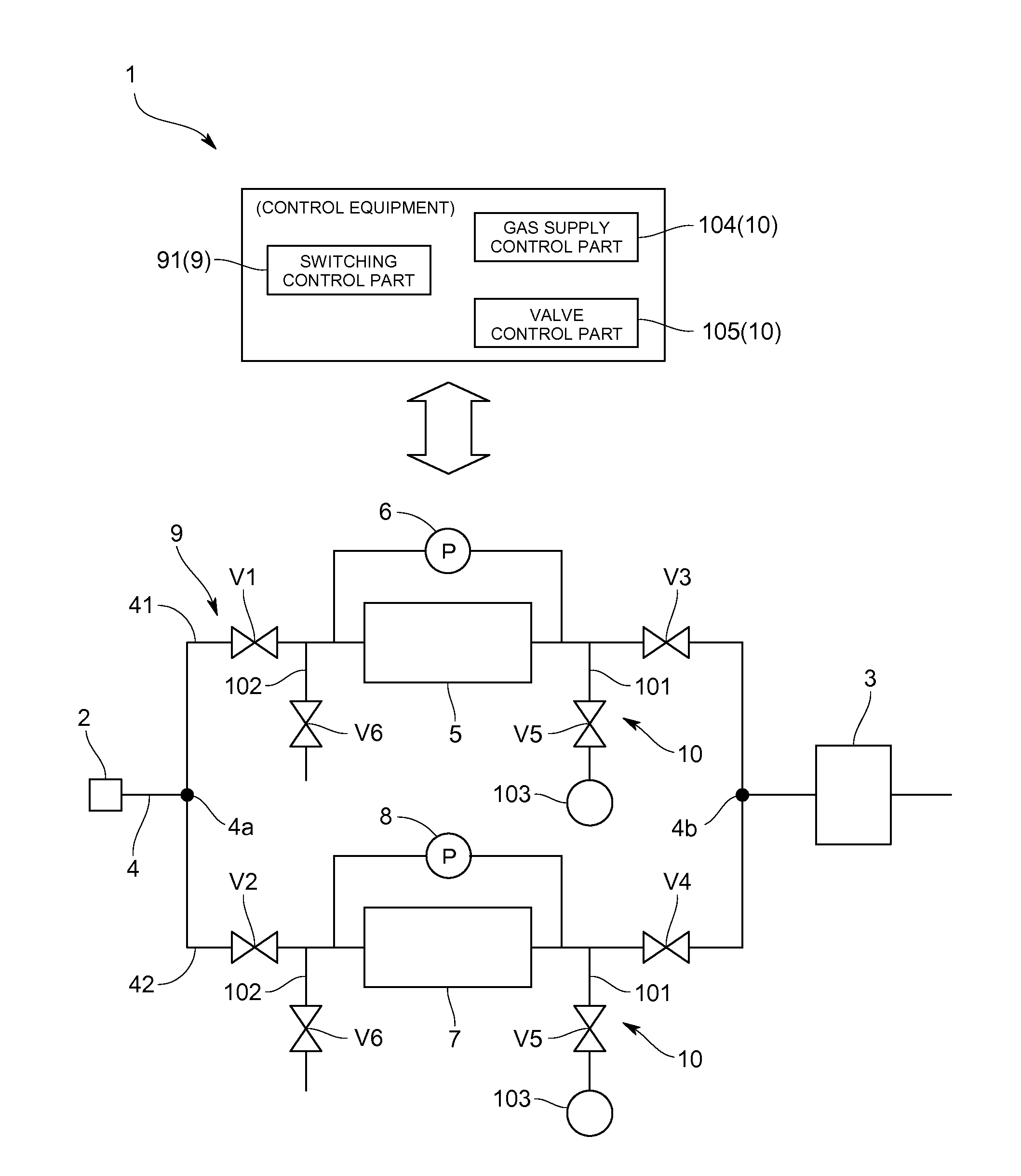
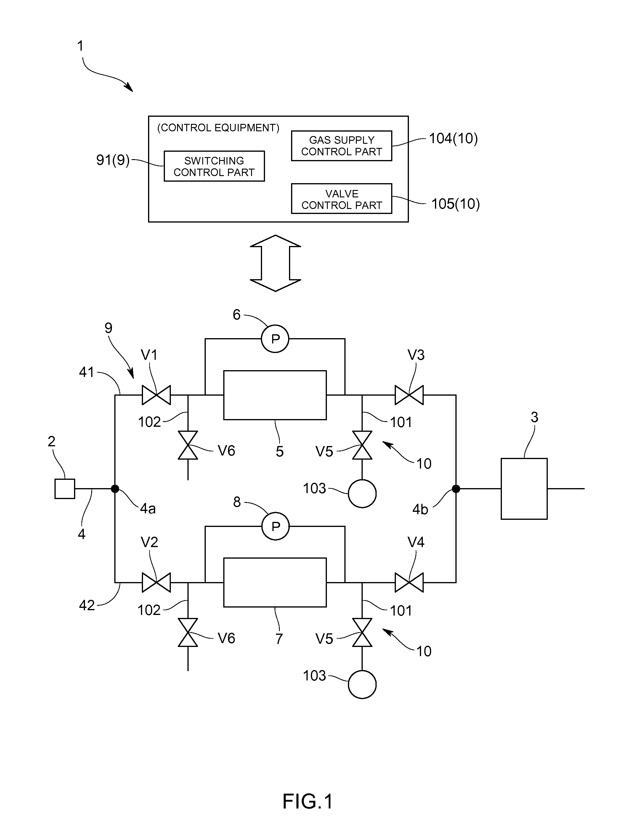
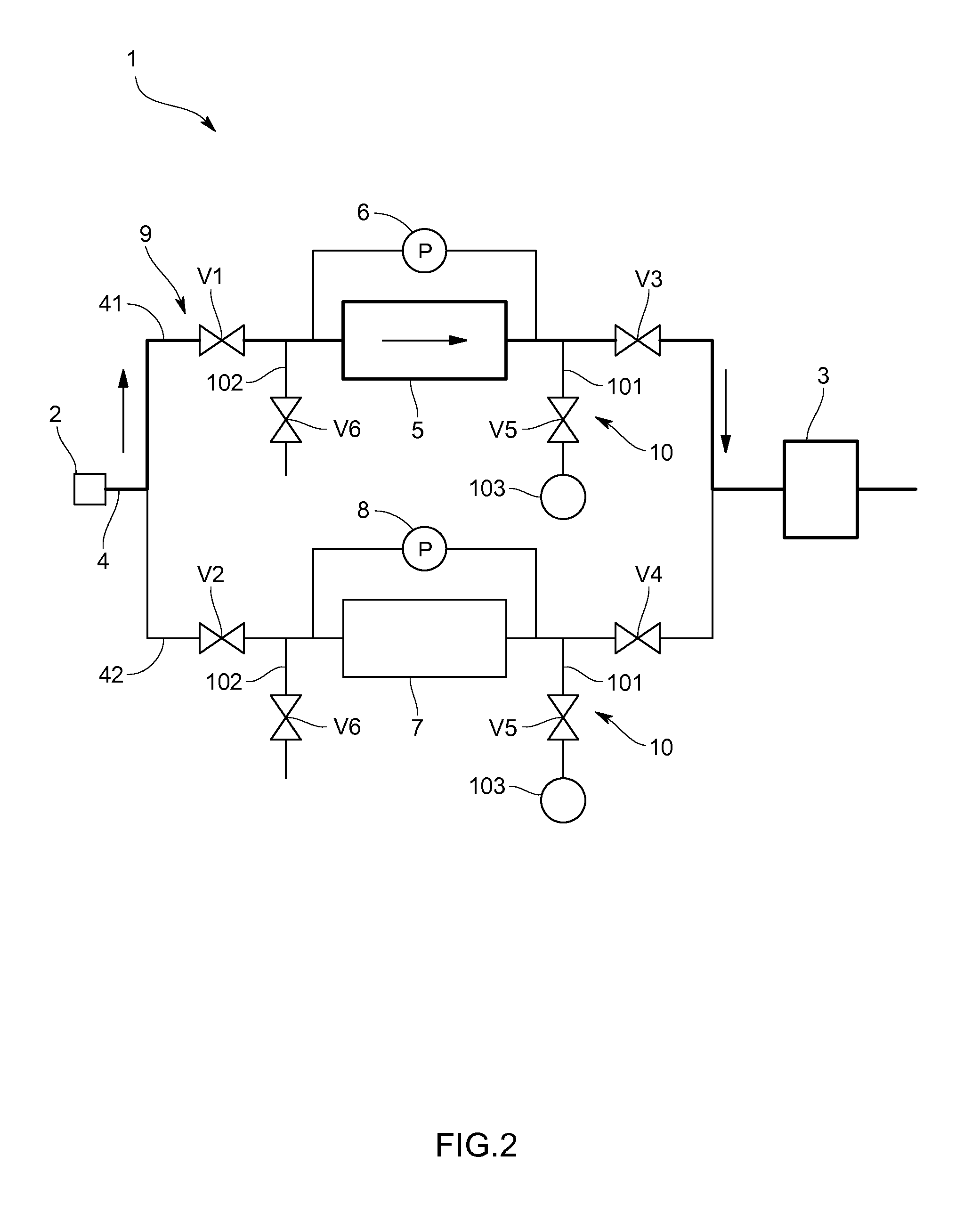
[0020]Specifically, as shown in FIG. 1, the exhaust gas analyzing apparatus 1 includes an introduction port 2 for introducing exhaust gas discharged from the engine, an exhaust gas analyzing part 3 for analyzing the exhaust gas introduced from the introduction port 2, and an introduction path 4 for connecting the introduction port 2 to the exhaust gas analyzing part 3 and guiding the exhaust gas introduced from the introduction port 2 to the exhaust gas anal...


PUM

PropertyMeasurementUnit
Pressureaaaaaaaaaa

Abstract

An exhaust gas analyzing apparatus provided a first filter flow path with a first filter, a second filter flow path provided with a second filter, an exhaust gas analyzing part for analyzing exhaust gas passing through the first filter or the second filter, a flow path switching mechanism for switching between the first filter flow path and the second filter flow path. A pulse purge mechanism is provided for supplying purge gas to the filters, in the filter flow paths, in a pulsed manner, and in the case where a pressure difference between an upstream side and a downstream side of the filter provided in one filter flow path where the exhaust gas flows becomes equal to or larger than a predetermined value, the one filter flow path is switched to the other one, and purge gas is supplied to the filter provided in the one filter flow path in the pulsed manner.

Description

CROSS-REFERENCE TO RELATED APPLICATION[0001]This application claims priority to JP Application No. 2012-117042, filed on May 22, 2012, the disclosure of which is incorporated in its entirety by reference herein.TECHNICAL FIELD[0002]The present invention relates to an exhaust gas analyzing apparatus for analyzing exhaust gas discharged from internal combustion engines of vehicles and the like or external combustion engines of steam turbines and the like.BACKGROUND ART[0003]As described in Japanese Patent JPA 2006-153746, in a conventional exhaust gas analyzing apparatus, an introduction path for introducing exhaust gas discharged from an engine installed in a test chamber is equipped with a dust filter for removing dusts and soot in the exhaust gas. The dust filter is clogged with adhered dusts and soot and thus, needs to be replaced periodically (for example, every eight hours).[0004]However, since the dust filter is often arranged in the test chamber, a user need to enter the test ...

Claims


Application Information

Patent Timeline
IPC IPC(8): B01D46/00
CPCG01N1/2247B01D46/0058G01N1/2252G01M15/102B01D46/90
Inventor MIYAI, MASARUYOSHIMURA, TOMOSHIITO, MANABU
Owner HORIBA LTD
Features
  • Generate Ideas
  • Intellectual Property
  • Life Sciences
  • Materials
  • Tech Scout
  • Unparalleled Data Quality
  • Higher Quality Content
  • 60% Fewer Hallucinations
Learn More