Projectile having a discardable sabot

a technology of projectiles and sabots, which is applied in the direction of projectiles, ammunition projectiles, weapons, etc., can solve the problems of projectiles shattered in weapon tubes or barrels, sabots being anchored to guided projectiles and/or penetrators, and malfunctions in discharge ballistics, so as to improve the transfer function or driving function, improve the separation function, and improve the separation function

Active Publication Date: 2013-11-28
RWM SCHWEIZ +1
View PDF7 Cites 5 Cited by
  • Summary
  • Abstract
  • Description
  • Claims
  • Application Information

AI Technical Summary

Benefits of technology

[0011]During firing, the bottom of the separation aid supports the hold of the projectile core in the sabot in an axial direction. The rear of the sabot is anchored at the bottom and is not able to open prematurely or separate prematurely, while in the weapon tube or barrel so the transfer function or driving function is improved. During exit from the weapon tube or barrel, the bottom and the fingers support symmetrical tearing and discarding of the sabot, as a result of which almost no impulse impact remains with respect to the projectile / penetrator, so separation function is improved.
[0012]In addition to the improvement in the separation function as well as in the transfer or driving function, the target accuracy also increases as a result of the almost impulse-free detachment of the sabot. Another benefit lies in the fact that the plastics extrusion method (plastic injection process), or the process of extruding plastic material (plastic injection molding), of the sabot decreases or even loses influence with respect to target accuracy.

Problems solved by technology

It is known that an asymmetrical or uneven separation and discarding of the sabots, or their segments, leads to a malfunction in discharge ballistics.
Another major problem is the anchoring of the sabot to the guided projectile and / or a penetrator.
It is possible that, as a result of the gas pressure of the propellant (i.e., a propellant powder) during firing and the thereby produced axial or radial acceleration force on the missile in the tube, the projectile is shattered in the weapon tube or barrel.
Unfortunately, this event does not occur symmetrically, i.e., the opening or tearing of the breaking points is asymmetrical.
As a result, the penetrator receives an impulse during ejection, resulting in potential wobbling or oscillation and diminished target accuracy.
Moreover, the manufacture of threading is expensive, which results in higher costs.

Method used


Image

  • Projectile having a discardable sabot
  • Projectile having a discardable sabot
  • Projectile having a discardable sabot

Examples


Embodiment Construction

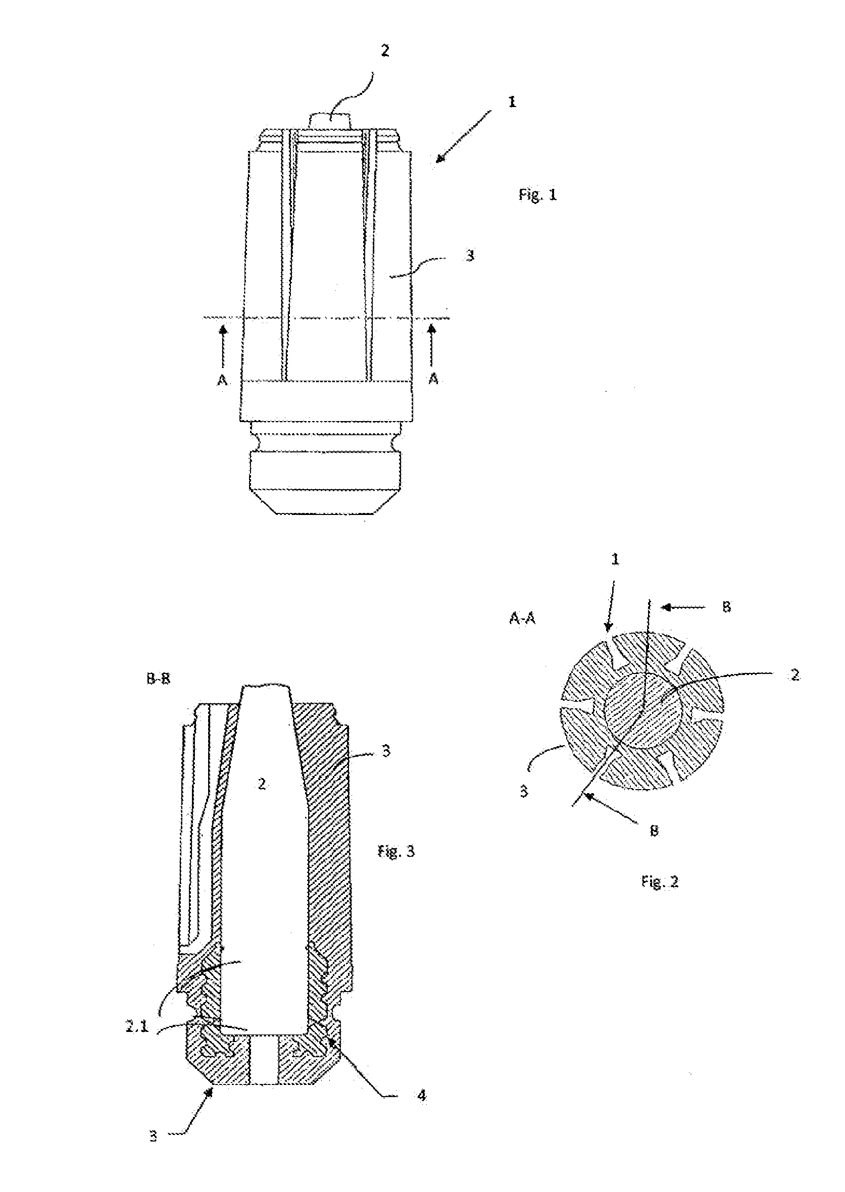
[0023]FIG. 1 depicts a projectile 1 provided with a projectile core 2 (i.e., a penetrator or projectile component), wherein the projectile core 2 is enclosed by a sabot 3. FIG. 2 depicts the projectile 1 in sectional view A-A from FIG. 1, and FIG. 3 depicts the sectional view B-B of the projectile from FIG. 2. Between the projectile core 2 and the sabot 3 is integrated, or arranged, a so-called separation aid 4 in the projectile bottom region 2.1 as shown in FIG. 3.

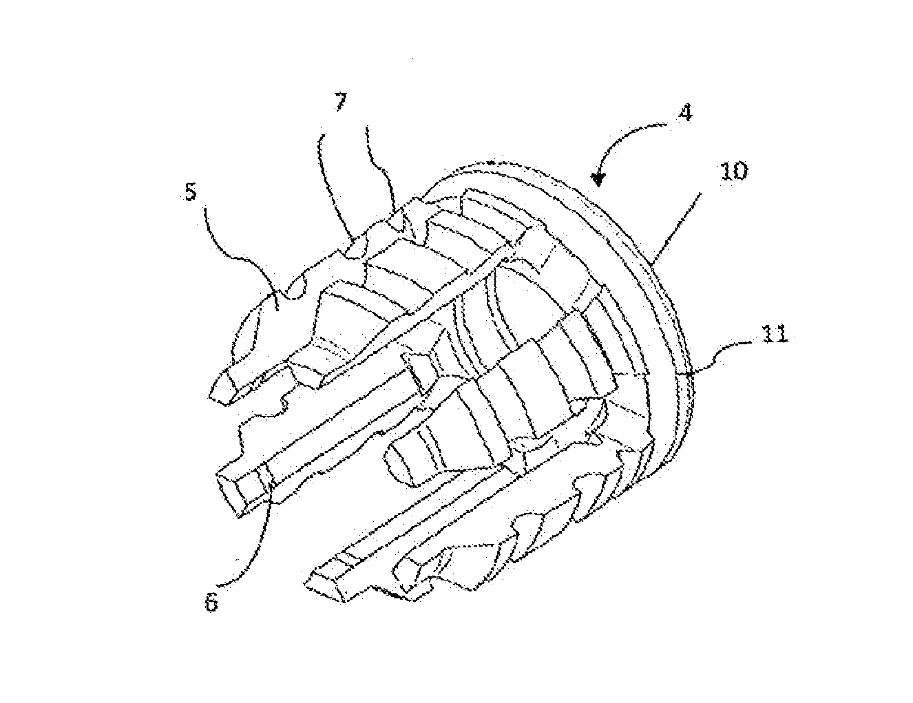
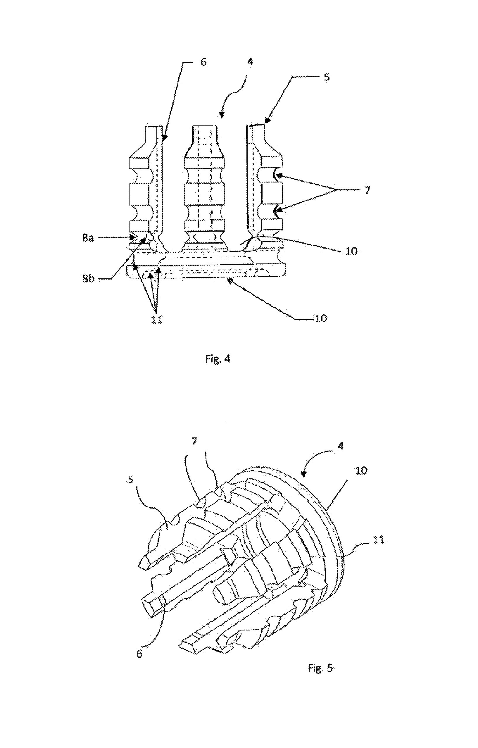
[0024]FIG. 4 and FIG. 5 depict an embodiment of the separation aid with six fingers 5, which are connected with each other by means of a ring or supporting surface 10. The separation aid 4 is attached to the core 2 by means of a bulge or bead 6 at the fingers 5. As shown in FIG. 5, the bulges / beads 6 are located on an interior side of the fingers 5, and each bulge or bead 6 is preferably integrated in the upper region of its corresponding finger 5. The number of fingers 5 can vary, whereby, in particular, the number of fi...


PUM


Abstract

The invention relates to a sabot (4) for a sub-caliber projectile (1) having a projectile core (2). When the projectile exits a weapon barrel, the sabot detaches from the projectile core (2) without transferring momentum by means of a separating aid (4) incorporated between the projectile core (2) and the sabot. The separating aid (4) has a plurality of fingers (5) having at least one predetermined breaking point (8a, 8b), which is connected to the projectile core (2) by a type of snap-connection bead (6) on the fingers/braces (5).

Description

[0001]This is a Continuation-in-Part Application in the United States of International Patent Application No. PCT / EP2011 / 004185 filed Aug. 19, 2011, which claims priority on German Patent Application No. DE 10 2010 045 474.5, filed Sep. 16, 2010. The entire disclosures of the above patent applications are hereby incorporated by reference.FIELD OF THE INVENTION[0002]The invention relates to a projectile having a discardable sabot for sub-caliber munitions, which is fired from a weapon tube or barrel equipped with angular grooves (e.g., rifling grooves of a rifled weapon tube).BACKGROUND OF THE INVENTION[0003]It is known that an asymmetrical or uneven separation and discarding of the sabots, or their segments, leads to a malfunction in discharge ballistics. The reason for this lies, among others, in (i) the premature opening of the back of the sabot inside the weapon tube or barrel and (ii) other than optimal tearing at the predetermined breaking points, following exit from the weapon...

Claims


Application Information

Patent Timeline
Patent Type & Authority Applications(United States)
IPC IPC(8): F42B14/06
CPCF42B14/064F42B14/06F42B14/08
Inventor ROSSMANN, RUDOLFKETELHUT, KAIBLACHE, ANDREAS
Owner RWM SCHWEIZ
Why Eureka
Try Eureka