
Grayscale redistribution system to improve retinal imaging by reducing the effect of a highly reflective optic nerve

a redistribution system and retinal camera technology, applied in the field of retinal cameras, can solve the problems of discomfort for patients, simply drowning out optic nerve detail, and even more difficult retinal imaging, and achieve the effects of capturing both optic nerve and retina detail, improving retinal camera picture quality, and allowing observation of retinal detail

Inactive Publication Date: 2008-02-26
ESCALON IP HLDG
View PDF2 Cites 1 Cited by
  • Summary
  • Abstract
  • Description
  • Claims
  • Application Information

AI Technical Summary

Benefits of technology

[0018]Since each of the outputs of the CCD array of the digital camera is addressable, one can arrange to weight the individual outputs of individual pixels of the CCD array so as to increase the transfer function between input and output for those input levels or intensities that are relatively low.
[0039]In summary, a system is provided to improve retinal camera picture quality by providing a user-variable transfer function for each pixel that results in redistributing grayscale values to solve the problem of saturation caused by highly reflective retinal objects. The result is the ability to capture both optic nerve and retina detail in a single picture. The darker retina is brightened using the redistributed grayscale values to permit observing retinal detail, while preserving optic nerve detail. The optic nerve and other highly reflective retinal objects are properly exposed by reducing flash lamp output to prevent saturation, while outputs of low-intensity pixels associated with the darker regions are intensified, in one embodiment in accordance with an adjustable Bezier curve. The result is that one can obtain retinal details previously flooded out by the reflections from the optic nerve while at the same time offering optic nerve detail. In one embodiment the redistributed grayscale values are optimized for each color plane to provide color-corrected images matching those associated with film cameras.

Problems solved by technology

A constant problem in retinal imaging is the fact that the optic nerve, which is basically where all of the nerve bundles go back to the brain, is very reflective.
More importantly, the optic nerves of the darker-skinned races, including the Negroid and Hispanic races, are in general more highly reflective than white or Caucasian races, making retinal imaging even more difficult.
However, if one increases the output of the xenon strobe normally used, one simply drowns out the optic nerve detail because of its high reflectivity.
This causes pain and is very uncomfortable for the patient.
However, the problem is not so much seeing the remainder of the optic nerve but dealing with the high reflections where the optic nerve is attached to the retina that visually resembles a hole in the back of the eye.
However, by cutting down the flash power to be able to observe the optic nerve detail, one has insufficient light to be able to view the remainder of the retina.
However, the problem of multiple pictures and flash lamp intensity versus optic nerve reflectivity has not as yet been resolved for the above reasons.

Method used


Image

  • Grayscale redistribution system to improve retinal imaging by reducing the effect of a highly reflective optic nerve
  • Grayscale redistribution system to improve retinal imaging by reducing the effect of a highly reflective optic nerve
  • Grayscale redistribution system to improve retinal imaging by reducing the effect of a highly reflective optic nerve

Examples


Embodiment Construction

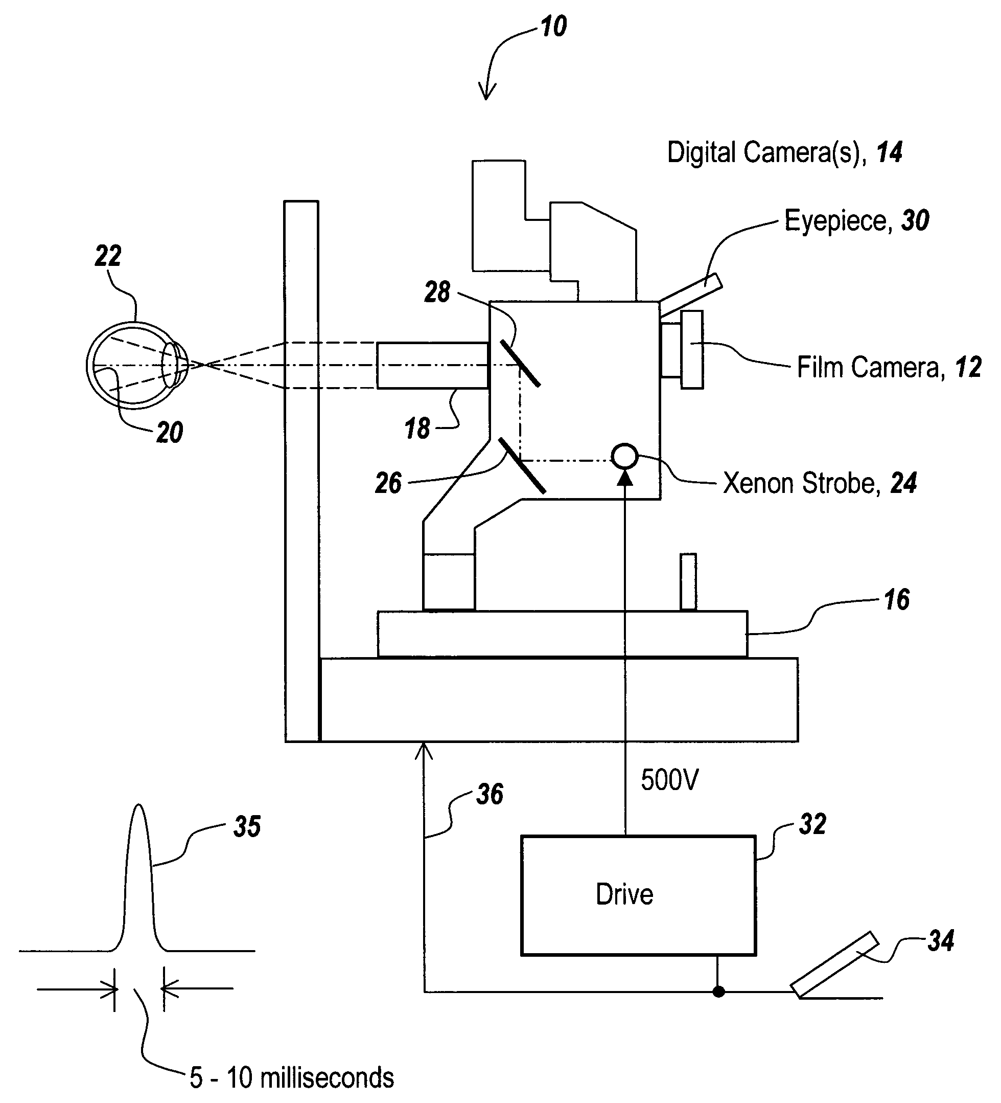
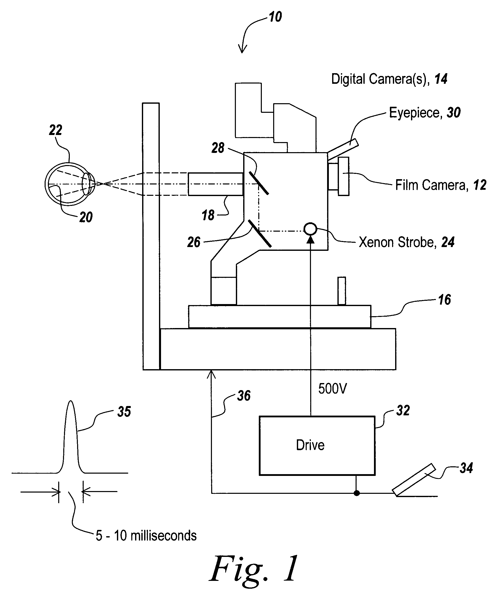
[0050]Referring now to FIG. 1, prior to discussing the subject retinal image optimization system, the operation of a typical retinal camera is discussed. Here a retinal imaging camera 10 includes a film camera 12 and a digital camera 14 mounted on a stand 16 such that an imaging system 18 images the retina 20 of eye 22 onto the focal planes of cameras 12 and 14. In order to illuminate retina 20, a xenon strobe lamp 24 has its output redirected by mirrors 26 and 28 out through imaging system 18 so that the output of xenon strobe 24 illuminates retina 20. Note that an eyepiece 30 is used for focusing both the digital and film camera as well as directing the optics to the appropriate portion of the eye.

[0051]A precise maximum strobe output includes the use of drive 32 that incorporates a power supply for delivering several hundred volts to the xenon strobe. As illustrated, this is accomplished by delivery of a several hundred-volt pulse 35, with a pulse width of between 5 and 10 millis...


PUM


Abstract

A system is provided to improve retinal camera picture quality by providing a user-variable transfer function for each pixel that results in redistributing grayscale values to solve the problem of saturation caused by highly reflective retinal objects. The result is the ability to capture both optic nerve and retina detail in a single picture. The darker retina is brightened to permit observing retinal detail using the redistributed grayscale values, while preserving optic nerve detail. Those pixels experiencing high-intensity reflections are properly exposed to prevent saturation, while outputs of low-intensity pixels associated with the darker regions are intensified, in one embodiment in accordance with an adjustable Bezier curve. The result is that one can obtain retinal details previously flooded out by the reflections from the optic nerve while at the same time offering optic nerve detail. In one embodiment the redistributed grayscale values are optimized for each color plane to provide color-corrected images matching those associated with film cameras.

Description

FIELD OF THE INVENTION[0001]This invention relates to retinal cameras and more particularly to a system for eliminating the effects of a highly reflective optic nerve so that detail of both the optic nerve and detail of the surrounding retinal material are viewable.BACKGROUND OF THE INVENTION[0002]In retinal imaging, one seeks to obtain photographs of the detail of the optic nerve and the surrounding retinal material that heretofore has been captured on film.[0003]A constant problem in retinal imaging is the fact that the optic nerve, which is basically where all of the nerve bundles go back to the brain, is very reflective. When one fires a strobe into the eye to illuminate the retina, the optic nerve tends to throw large amounts of light back at the camera, which shows up as a bright blotch at the position where the optic nerve is attached to the retina. The rest of the detail of the retina that one wants to see, especially at the periphery, is very dark. The result of photographi...

Claims


Application Information

Patent Timeline
Patent Type & Authority Patents(United States)
IPC IPC(8): A61B3/00G06K9/00H04N5/222
CPCA61B3/14
Inventor CARNEVALE, MATTHEW
Owner ESCALON IP HLDG
Learn More